
Page 97 - Subyek Computer Aided Design - [David Planchard] Engineering Design with SOLIDWORKS
P. 97
Engineering Design with SOLIDWORKS® 2018 Fundamentals of Part Modeling
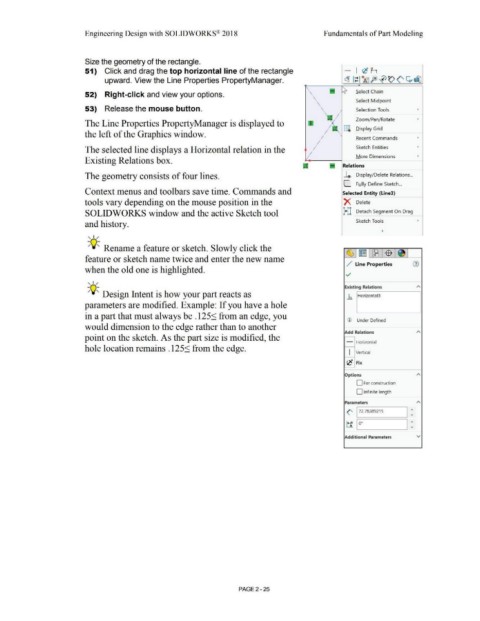
Size the geometry of the rectangle.
51) Click and drag the top horizontal line of the rectangle - I e! h
upward. View the Line Properties PropertyManager. ~ ,~ ~ foJ 0<:)(' ~ej]
' Select Chain
52) Right-click and view your options. \ '
\ Select Midpoint
\
53) Release the mouse button. \ Selection Tools •
I
Zoom/Pan/Rotate •
The Line Properties PropertyManager is displayed to
, I §i D.isplay Grid
the left of the Graphics window. I I Recent Commands •
, I
The selected line displays a Horizontal relation in the I Sketch Entities •
, I More Dimensions •
Existing Relations box.
Relations
The geometry consists of four lines. ~ Display/Delete Relations ...
C. Fully Define Sketch ...
Context menus and toolbars save time. Commands and Selected Entity (Line3)
tools vary depending on the mouse position in the X Delete
SOLIDWORKS window and the active Sketch tool l+] Detach Segment On Drag
and history. Sketch Tools •
, ,/
-;Q~ Rename a feature or sketch. Slowly click the
~ ~ l_~_I $ J~ I
feature or sketch name twice and enter the new name
/ Line Properties G)
when the old one is highlighted.
../
, ,/
Existing Relations A
-;Q~ Design Intent is how your part reacts as .h. Horizontal3
parameters are modified. Example: If you have a hole
in a part that must always be .125:S from an edge, you
CD Under Defined
would dimension to the edge rather than to another
Add Relations A
point on the sketch. As the part size is modified, the
- Horizontal
hole location remains .125:S from the edge.
I Vertical
e_e Fix
Options A
D For construction
D Infinite length
Parameters A
(' 172.78389215 I :
~ Io· I :
Additional Parameters v
PAGE 2 - 25