
Page 101 - Subyek Computer Aided Design - [David Planchard] Engineering Design with SOLIDWORKS
P. 101
Engineering Design with SOLIDWORKS® 2018 Fundamentals of Part Modeling
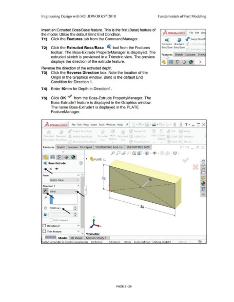
Insert an Extruded Boss/Base feature. This is the first (Base) feature of 7.
the model. Utilize the default Blind End Condition. pS SOLIDWORKS File Edit Vie
71) Click the Features tab from the Command Manager. J° Swept Boss/B
Extruded Revolved Lofted Bossie
72) Click the Extruded Boss/Base ~ tool from the Features Boss/Base Boss/Base
Bovnrlarv Rn
toolbar. The Boss-Extrude PropertyManager is displayed. The
Fea ures Sketch Evaluate DimX
extruded sketch is previewed in a Trimetric view. The preview
displays the direction of the extrude feature. >
Reverse the direction of the extruded depth.
73) Click the Reverse Direction box. Note the location of the
Origin in the Graphics window. Blind is the default End
Condition for Direction 1.
74) Enter 10mm for Depth in Direction1.
75) Click OK ~ from the Boss-Extrude PropertyManager. The
Boss-Extrude1 feature is displayed in the Graphics window.
The name Boss-Extrude1 is displayed in the PLATE
FeatureManager.
7. 8 ?·_o x
pS SOLIDWORKS File Edit View Insert Tools Window Help 'JI'
Swept Boss/Base Swept Cut Wrap
'.:ict:ruded Revolved Lofted Boss/Base Extruded Hole Revolved Lofted Cut Fillet Linear »
,ss/Base Boss/Base Cut Wizard Cut Pattern
Boundarv Boss/Base .... Boundary Cut .... .... Shell J Mirror
Features Sketch Evaluate DimXpert SOLIDWORKS Add-Ins SOLIDWORKS MBD DD - [51 x
- Q ·
I ~ ~ PLATE ( ...
dfl Boss-Extrude (1)
x ®
From
[sketch Plane
Direction 1
y
I Draft outward
D Direction 2 v x
D Thin Feature v
--------- " *Trimetric
Model 30 Views Motion Stud 1
..
•
53.06mm Omm Full Defined Editin Sketch1 MMGS • ...
PAGE 2 - 29