Page 104 - Subyek Computer Aided Design - [David Planchard] Engineering Design with SOLIDWORKS
P. 104

FundamentaJs of Part Modeling                                 Engineering Design with SOLfDWORKS" 2018


                     ,,,

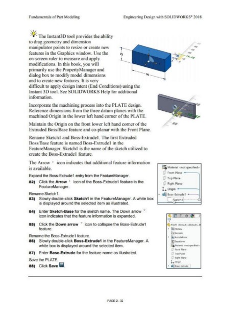
                     ~Q~ The lnstant3D tool provides the ability
                    to drag geo1uetry and dimension
                    manipulator points to resize or create new  r-                                               ~ :--,.,,__ ..
                                                                                                                              ...
                                                                                                                             / ..,
                    features in the Graphics window. Use the                   f                                 ,_p,;, ,, ,, . .,.,
                    on-screen ruler to 1ueasure and apply                      ..._____
                                                                                                                      •
                    modifications. In this book, you will
                    primarily use the PropertyManager and
                    dialog box to modify model dimensions
                    and to create new features. It is very
                    difficult to apply design intent (End Conditions) using the

                    Instant 30 tool. See SOLIDWORKS Help for additional
                    infonnation.

                    Incorporate the machining process into the PLATE design.
                    Reference dimensions from the three datu1n planes with the

                    machined Origin in the lower left hand comer of the PLATE.

                    Maintain the Origin on the front lower left hand comer of the
                    Extruded Boss/Base feature and co-planar with the Front Plane.


                    Rename Sketch I and Boss-Extrude!. The first Extruded
                    Boss/Base feature is named Boss-Extrude I in the
                    FeatureManager. Sketch I is the name of the sketch utilized to
                    create the Boss-Extrude I feature.


                    The Arrow •  icon indicates that additional feature infonuation
                                                                                                           0-
                    is avai !able.                                                                         ::.a Matenal  <not speafied>
                                                                                                           CJ Pront Pl&ne  -  -~
                    Expand the Boss-Extrude1 entry from the FeatureManage<.
                                                                                                           CJ  Top Plane
                    82)  Click the Arrow  •  icon of the Boss-Extrude1 feature in the
                                                                                                           CJ R;ght Plane
                          FeatureManager.
                                                                                                           L  Ongm  -   -----.J
                    Rename Sketch1.                                                                     ....  ~ Boss-Ertrude 1  ----.J
                    83)  Slowly double-click Sketch1 in the FeatureManager. A whrte box                       [L  Retch1!··   ••  · ,C
                          is displayed around the selected rtem as illustrated.


                    84)  Enter Sketch-Base for the sketch name. The Down arrow  •
                          icon indicates that the feature information is expanded.

                    85)  Click the Down arrow  •  icon to collapse the Boss-Extrude1                          .  Pl.ATE  (Ocfaoult«Ocf.ilA:>.0
                          feature.                                                                             •  [i}H61o,y
                                                                                                                 €tJ SC'nsors
                    Rename the Boss-Extrude1 feature.
                                                                                                               •  [il.tmM lilllotll
                    86)  Slowly double-click Boss-Extrude1 in the FeatureManager. A                              {'.tj(i:,w.io11s.
                          white box is displayed around the selected item.                                       F.i Mlllofftal  <ncn $pkiUll4>
                                                                                                                 O front Pti,r,e
                    87)  Enter Base-Extrude for the feature name as illustrated.                                 {!:I  fQSI Fl.tltlt
                                                                                                                 r;J  R,ght Pltne
                    Save the PLATE.                                                                              L. 0119'(1
                    88)  Click Save lil.                                                                       •  "'1.S.,se·f.11\,de,n


                                                                       PAGE2 · 32
   99   100   101   102   103   104   105   106   107   108   109