
Page 113 - Subyek Computer Aided Design - [David Planchard] Engineering Design with SOLIDWORKS
P. 113
Engineering Design with SOLIDWORKS® 2018 Fundamentals of Part Modeling
\ . t~ 1~ ~ .~ [~ .$ [~ !
!'""""""'' 0
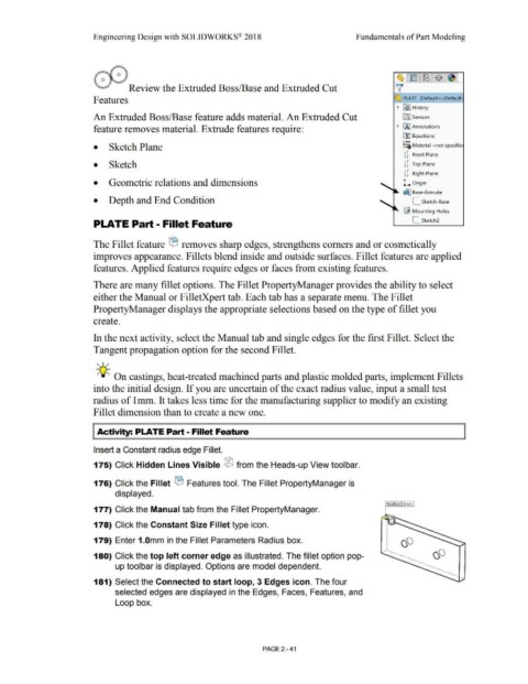
~ Review the Extruded Boss/Base and Extruded Cut v
Features ~ PLATE (Default<<Default
• ~ I History
An Extruded Boss/Base feature adds material. An Extruded Cut ~ Sensors
feature removes material. Extrude features require: • IA] Annotations
ll:J Equations
o-
• Sketch Plane ~=D Material <not specifie
Q Front Plane
• Sketch Q Top Plane
Q Right Plane
• Geometric relations and dimensions L Origin
~ Base-Extrude
• Depth and End Condition [_ Sketch-Base
~ Mounting Holes
PLATE Part - Fillet Feature [_ Sketch2
The Fillet feature tB removes sharp edges, strengthens comers and or cosmetically
improves appearance. Fillets blend inside and outside surfaces. Fillet features are applied
features. Applied features require edges or faces from existing features.
There are many fillet options. The Fillet PropertyManager provides the ability to select
either the Manual or FilletXpert tab. Each tab has a separate menu. The Fillet
PropertyManager displays the appropriate selections based on the type of fillet you
create.
In the next activity, select the Manual tab and single edges for the first Fillet. Select the
Tangent propagation option for the second Fillet.
, ,/
-;Q~ On castings, heat-treated machined parts and plastic molded parts, implement Fillets
into the initial design. If you are uncertain of the exact radius value, input a small test
radius of lmm. It takes less time for the manufacturing supplier to modify an existing
Fillet dimension than to create a new one.
I Activity: PLATE Part - Fillet Feature
Insert a Constant radius edge Fillet.
175) Click Hidden Lines Visible ® from the Heads-up View toolbar.
176) Click the Fillet ® Features tool. The Fillet PropertyManager is
displayed.
Radius: l mm
177) Click the Manual tab from the Fillet PropertyManager.
•
178) Click the Constant Size Fillet type icon. :'--"-
•
•
•
•
•
•
•
179) Enter 1.0mm in the Fillet Parameters Radius box. •
•
•
•
•
•
.. -.....
180) Click the top left corner edge as illustrated. The fillet option pop- .. ...
up toolbar is displayed. Options are model dependent. ·- ·- ·- •
·-.
.. .... ..
181) Select the Connected to start loop, 3 Edges icon. The four
selected edges are displayed in the Edges, Faces, Features, and
Loop box.
PAGE 2-41