
Page 10 - Engineering drawing from first principles using AutoCAD
P. 10
First steps' 3
Commend:
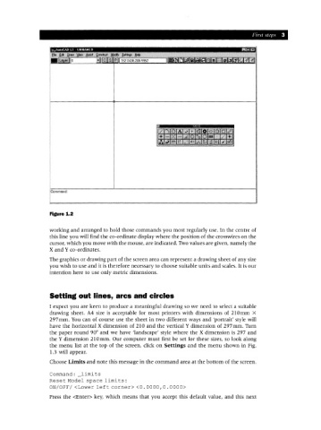
Figure 1.2
working and arranged to hold those commands you most regularly use. In the centre of
this line you will find the co-ordinate display where the position of the crosswires on the
cursor, which you move with the mouse, are indicated. Two values are given, namely the
X and Yeo-ordinates.
The graphics or drawing part of the screen area can represent a drawing sheet of any size
you wish to use and it is therefore necessary to choose suitable units and scales. It is our
intention here to use only metric dimensions.
Setting out lines, arcs and circles
I expect you are keen to produce a meaningful drawing so we need to select a suitable
drawing sheet. A4 size is acceptable for most printers with dimensions of 210 mm X
297mm. You can of course use the sheet in two different ways and 'portrait' style will
have the horizontal X dimension of 210 and the vertical Y dimension of 297mm. Turn
the paper round 90° and we have 'landscape' style where the X dimension is 297 and
the Y dimension 210 mm. Our computer must first be set for these sizes, so look along
the menu list at the top of the screen, click on Settings and the menu shown in Fig.
1.3 will appear.
Choose Limits and note this message in the command area at the bottom of the screen.
Command: limits
Reset Model space limi ts :
ON/OFF/ <Lower left corner> <0.0000,0.0000>
Press the <Enter> key, which means that you accept this default value, and this next