
Page 11 - Engineering drawing from first principles using AutoCAD
P. 11
4 Engineering drawinq [rom [irst principles
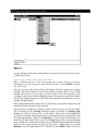
Figure 1.3
message will appear (Note that drawing limits are always quoted with the X and Yvalues
in alphabetical order):
Upper right corner <420.0000,297.0000>
This is a default value for a sheet of A3 paper and is double the size we require.
Furthermore, it is the wrong way round for portrait style, so type 210,297 and press
the <Enter> key.
Note that the area at the bottom of the screen links us with the computer to exchange
messages. We cannot indicate our next move until the computer shows Command: This
message means that it is now ready to receive details of the next operation. After
choosing the next event from the dropdown menu, it is necessary to press the <Enter>
key and the computer then goes to work. When the operation is complete the Command:
message will again appear.
Please understand that this symbol <R> or .J means that you press the <Enter> key and
obviously looks like the key on the keyboard.
Having selected a suitable size of paper on which to draw, we want it to become visible.
This is activated via the Settings pull-down menu by clicking the Drawing Aids
dialogue box. The box shown in Fig. 1.4 will appear. Click to turn on the Grid which
is a series of accurately spaced dots forming a square grid and can conveniently be used
for measuring purposes. Adjust the X Spacing to 10.00 and you will find that the Y
SPACING will adjust itself. Click to turn on the Snap feature. This is a most important
item, enabling you to position exactly the cursor at specified distances apart and certainly
speeds up the accurate placing of points on the screen. I suggest that you set an X
Spacing of 2.00 and again ignore the Y SPACING. In the Modes column at the left-