
Page 14 - Engineering drawing from first principles using AutoCAD
P. 14
First steps 7
ttlAutoCAD IT, UNNAMED RIilEi
TOOLBOX SYMBOL ZOOM BUTTON
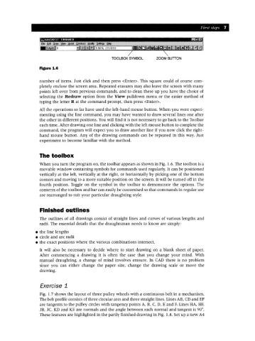
Figure 1.6
number of items. Just click and then press <Enter>. This square could of course com-
pletely enclose the screen area. Repeated erasures may also leave the screen with many
points left over from previous commands, and to clean these up you have the choice of
selecting the Redraw option from the View pulldown menu or the easier method of
typing the letter R at the command prompt, then press <Enter>.
All the operations so far have used the left-hand mouse button. When you were experi-
menting using the line command, you may have wanted to draw several lines one after
the other in different positions. You will find it is not necessary to go back to the Toolbar
each time. After drawing one line and clicking with the left mouse button to complete the
command, the program will expect you to draw another line if you now click the right-
hand mouse button. Any of the drawing commands can be repeated in this way. Just
experiment to become familiar with the method.
The toolbox
When you turn the program on, the toolbar appears as shown in Fig. 1.6. The toolbox is a
movable window containing symbols for commands used regularly. It can be positioned
vertically at the left, vertically at the right, or horizontally by picking one of the bottom
corners and moving to a more suitable position on the screen. It will be turned off in the
fourth position. Toggle on the symbol in the toolbar to demonstrate the options. The
contents of the toolbox and bar can easily be customised so that commands in regular use
are rearranged to suit your particular draughting style.
Finished outlines
The outlines of all drawings consist of straight lines and curves of various lengths and
radii. The essential details that the draughtsman needs to know are simply:
• the line lengths
• circle and arc radii
• the exact positions where the various combinations intersect.
It will also be necessary to decide where to start drawing on a blank sheet of paper.
After commencing a drawing it is often the case that you change your mind. With
manual draughting, a change of mind involves erasure. In CAD there is no problem
since you can either change the paper size, change the drawing scale or move the
drawing.
Exercise 1
Fig. 1.7 shows the layout of three pulley wheels with a continuous belt in a mechanism.
The belt profile consists of three circular arcs and three straight lines. Lines AB, CDand EF
are tangents to the pulley circles with tangency points A, B, C, D, E and F. Lines HA, HF,
JB, JC, I(D and I(E are normals and the angle between each normal and tangent is 90°.
These features are highlighted in the partly finished drawing in Fig. 1.8. Set up a new A4