
Page 19 - Engineering drawing from first principles using AutoCAD
P. 19
12 Engineering drawinq [rom [irst principles
65 55
o
C\I
LO
LO
050
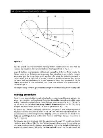
Figure 1.11
Type the letter C for close followed by pressing <Enter> and the circle will close with the
required line thickness. Save your completed drawing as shown in Fig. 1.11.
You will find that some programs will not edit a complete circle, but if you require the
thinner circle, as we do in this case to use as a dimension line, it can easily be redrawn
afterwards. Edit the centre lines neatly as shown by using the BREAI( command to
remove small gaps as indicated. It is good practice to position the centre lines so that
the centre itself is marked clearly by a cross. Try to make centre lines symmetrical. Use the
BREAI( command to clear unwanted lines. Save your solution fully dimensioned as
shown in stage 3.
Before proceding, however, please refer to the general dimensioning notes on page 110.
Printing procedure
A print is now required of the completed pulley layout drawing and I assume a printer has
already been installed and configured. Select the Print/Plot option from the File menu
and the Plot Configurati6n dialogue box will appear on the screen (Fig. 1.12). Click at the
top left corner on the Print/Plot Setup Default Selection option and the Print Setup
dialogue box appears and confirms the printer specification (Fig. 1.13).
My printer is a Canon BJ-230 using standard A4 size paper. Check that your printer is
listed and the other details are as above. Click OK. The Print/Plot Setup box returns. We
need a copy of the screen image so select Display. Check the paper size box. Click on the
Rotation and Origin button and the Plot Rotation and Origin dialogue box shown in
Fig. 1.14 appears.
The drawing has been produced with the paper turned through 90°, so click on the plot
rotation setting of 90 and OK. The first Plot Configuration box returns. Toensure that our
print isthe maximum sizefor the paper area available, click on the Scaled to Fit box in the
bottom right-hand corner. Clickon the Preview and Full buttons and the print details will