
Page 44 - Engineering drawing from first principles using AutoCAD
P. 44
· Geometrical applications 37
066
R10
R50
o
LO
o
LO
~
I.. 070 .1
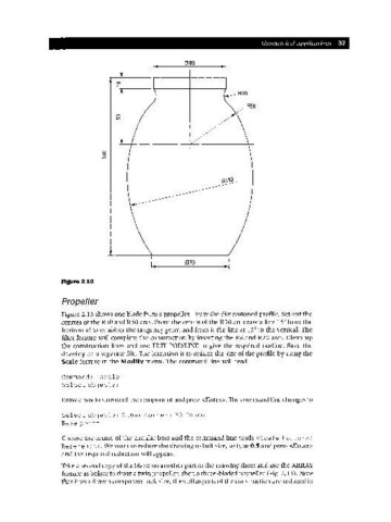
Figure 2.10
Propeller
Figure 2.13 shows one blade from a propeller. Draw the dimensioned profile. Set out the
centres of the R30 and RSO arcs. From the centre of the R30 arc draw a line ISofrom the
horizontal to establish the tangency point and from it the line at ISO to the vertical. The
fillet feature will complete the construction by inserting the R8 and R20 arcs. Clean up
the construction lines and use EDIT POLYLINE to give the required outline. Save the
drawing on a separate file. The intention is to reduce the size of the profile by using the
Scale feature in the Modify menu. The command line will read
Command: scale
Select obj ects:
Draw a box to surround the component and press <Enter>. The command line changes to
Select obj ects: Other corner: 35 found
Base point
Choose the centre of the circular boss and the command line reads <Scale factor>/
Reference:. We want to reduce the drawing to half size, so type 0.5 and press <Enter>
and the required reduction will appear.
Take a second copy of the blade on another part of the drawing sheet and use the ARRAY
feature as before to draw a twin propeller, then a three-bladed propeller (Fig. 2.13). Note
that if you draw a component half size, then all aspects of the construction are reduced in