
Page 49 - Engineering drawing from first principles using AutoCAD
P. 49
42 Engineering drawinq [rom first principles
A
NORMAL F2 D
R80-
B
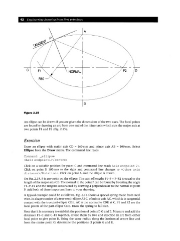
Figure 2.15
An ellipse can be drawn if you are given the dimensions of the two axes. The focal points
are found by drawing an arc from one end of the minor axis which cuts the major axis at
two points Fl and F2 (Fig. 2.15).
Exercise
Draw an ellipse with major axis CD = 160mm and minor axis AB = 100mm. Select
Ellipse from the Draw menu. The command line reads
Command: _ellipse
<Axis endpointl>/centre:
Click on a suitable position for point C and command line reads Axis endpoint 2:.
Click on point D 180mm to the right and command line changes to <Other axis
distance>/Rotation:. Click on point A and the ellipse is drawn.
On Fig. 2.15, P is any point on the ellipse. The sum of lengths FI-P + P-F2 is equal to the
length of the major axis CD.The normal to the point P can be found by bisecting the angle
FI-P-F2 and the tangent constructed by drawing a perpendicular to the normal at point
P. Add both of these important lines to your drawing.
A typical example could be as follows. Fig. 2.16 shows a special spring made from steel
wire. Its shape consists of a true semi-ellipse ABC, of minor axis AC, which is in tangential
contact with the true part-ellipse CDE. AC is the normal to CDE at C. Fl and F2 are the
focal points of the part-ellipse CDE. Draw the spring to full size.
Note that it is necessary to establish the position of points D Gand E. Measure and add the
distances FI-C and C-F2 together, divide them by two and describe an arc from either
focal point to give point D. Using the same radius along the horizontal centre line and
from the centre point 0, determine the positions of points G and E.