
Page 52 - Engineering drawing from first principles using AutoCAD
P. 52
Geometrical applications 45
of the arrow and another point above and to the right of the arrow. The command line
now reads <Base poin t or displacemen t> /Mul tiple:. Click on the arrow tip. The
command line reads Second poin t of displacemen t: .Click on a point about I5mm
vertically below and the copy arrow appears.
It is now necessary to reduce the size of the arrow so select Scale from the Modify menu
and the command line reads Select obj ects :. Draw a box as described above to
enclose the arrow and the command line reads Base point:. Click on the tip of the
arrow and the command line reads <Scale factor>/Reference:. Type 0.75 and
press <Enter>. The reduced size arrow is drawn.
Repeat the procedure for the third arrow with a scale factor of 0.5. Select the Move
command from the Modify menu to reposition the arrows on the ellipse as follows. The
command line reads Select obj ects :. Draw a box enclosing the arrow and press
<Enter>. The command line reads Base point or displacement:. Click on the centre
point of the tail of the arrow and the command line changes to Second point of
displacement:. Reposition the arrow on the ellipse.
The arrow will now be in the horizontal position with its tail on the correct spot but needs
to be rotated so that its tip also lines up with the profile of the ellipse. Select Rotate from
the Modify menu and the command line reads
Command: rotate
Select obj ects :
Draw a box enclosing the arrow and enter and command line reads Base point:. Click
on the centre of the tail and the command line reads <Rotation angle>/Refer-
ence : . The arrow will now rotate so reposition the tip on the ellipse profile and click
again to enter.
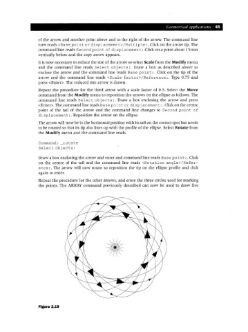
Repeat the procedure for the other arrows, and erase the three circles used for marking
the points. The ARRAY command previously described can now be used to draw five
Figure 2.19