
Page 48 - Engineering drawing from first principles using AutoCAD
P. 48
Geometrical applications 41
30
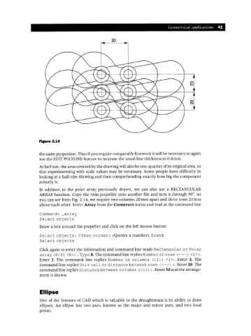
Figure 2.14
the same proportion. Thus if you require comparable linework it will be necessary to again
use the EDITPOLYLINE feature to increase the usual line thickness to 0.4mm.
At half size, the area covered by the drawing will also be one-quarter of its original area, so
that experimenting with scale values may be necessary. Some people have difficulty in
looking at a half-size drawing and then comprehending exactly how big the component
actually is.
In addition to the polar array previously drawn, we can also use a RECTANGULAR
ARRAY function. Copy the twin propeller onto another file and turn it through 90°. As
you can see from Fig. 2.14, we require two columns 20mm apart and three rows 20mm
above each other. Select Array from the Construct menu and read at the command line
Command: _array
Select obj ects
Draw a box around the propeller and click on the left mouse button:
Select obj ects: Other corner: (Quotes a number) found
Select obj ects
Click again to enter the information and command line reads Rectangular or Polar
array (RIP) <R>:. Type R. The command line replies Number of rows (---) <1>:.
Enter 3. The command line replies Number of columns (111) <1>:. Enter 2. The
command line replies Uni t cell or dis tance between rows (- - -) :. Enter 20. The
command line replies Dis tance between columns (111) :. Enter 30 and the arrange-
ment is drawn.
Ellipse
One of the features of CAD which is valuable to the draughtsman is its ability to draw
ellipses. An ellipse has two axes, known as the major and minor axes, and two focal
points.