
Page 104 - Enhanced Oil Recovery in Shale and Tight Reservoirs
P. 104
Huff-n-puff injection in shale gas condensate reservoirs 91
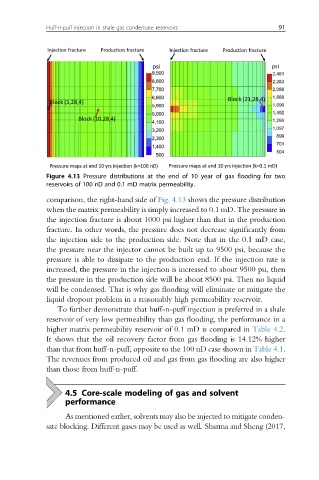
Figure 4.13 Pressure distributions at the end of 10 year of gas flooding for two
reservoirs of 100 nD and 0.1 mD matrix permeability.
comparison, the right-hand side of Fig. 4.13 shows the pressure distribution
when the matrix permeability is simply increased to 0.1 mD. The pressure in
the injection fracture is about 1000 psi higher than that in the production
fracture. In other words, the pressure does not decrease significantly from
the injection side to the production side. Note that in the 0.1 mD case,
the pressure near the injector cannot be built up to 9500 psi, because the
pressure is able to dissipate to the production end. If the injection rate is
increased, the pressure in the injection is increased to about 9500 psi, then
the pressure in the production side will be about 8500 psi. Then no liquid
will be condensed. That is why gas flooding will eliminate or mitigate the
liquid dropout problem in a reasonably high permeability reservoir.
To further demonstrate that huff-n-puff injection is preferred in a shale
reservoir of very low permeability than gas flooding, the performance in a
higher matrix permeability reservoir of 0.1 mD is compared in Table 4.2.
It shows that the oil recovery factor from gas flooding is 14.12% higher
than that from huff-n-puff, opposite to the 100 nD case shown in Table 4.1.
The revenues from produced oil and gas from gas flooding are also higher
than those from huff-n-puff.
4.5 Core-scale modeling of gas and solvent
performance
As mentioned earlier, solvents may also be injected to mitigate conden-
sate blocking. Different gases may be used as well. Sharma and Sheng (2017,