
Page 379 - Enhanced Oil Recovery in Shale and Tight Reservoirs
P. 379
Fracturing fluid flow back 351
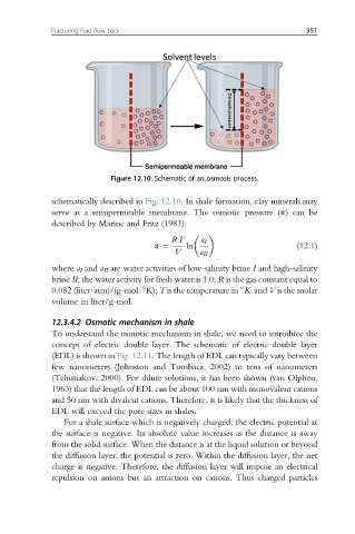
Figure 12.10 Schematic of an osmosis process.
schematically described in Fig. 12.10. In shale formation, clay minerals may
serve as a semipermeable membrane. The osmotic pressure (p) can be
described by Marine and Fritz (1981):
RT a I
p ¼ ln (12.1)
V a II
where a I and a II are water activities of low-salinity brine I and high-salinity
brine II; the water activity for fresh water is 1.0; R is the gas constant equal to
0.082 (liter$atm)/(g-mol$ K); T is the temperature in K, and V is the molar
volume in liter/g-mol.
12.3.4.2 Osmotic mechanism in shale
To understand the osmotic mechanism in shale, we need to introduce the
concept of electric double layer. The schematic of electric double layer
(EDL) is shown in Fig. 12.11. The length of EDL can typically vary between
few nanometers (Johnston and Tombacz, 2002) to tens of nanometers
(Tchistiakov, 2000). For dilute solutions, it has been shown (van Olphen,
1963) that the length of EDL can be about 100 nm with monovalent cations
and 50 nm with divalent cations. Therefore, it is likely that the thickness of
EDL will exceed the pore sizes in shales.
For a shale surface which is negatively charged, the electric potential at
the surface is negative. Its absolute value increases as the distance is away
from the solid surface. When the distance is at the liquid solution or beyond
the diffusion layer, the potential is zero. Within the diffusion layer, the net
charge is negative. Therefore, the diffusion layer will impose an electrical
repulsion on anions but an attraction on cations. Thus charged particles