
Page 61 - Enhanced Oil Recovery in Shale and Tight Reservoirs
P. 61
Huff-n-puff gas injection in oil reservoirs 49
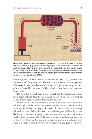
Figure 2.41 Schematic of a supercritical fluid extraction system. The supercritical fluid
(e.g., CO 2 ) (red [light gray in print version]) is pumped to the extraction vessel where the
analytes (purple [dark gray in print version]) are extracted from the sample matrix
(brown [black in print version]). The analytes are then swept through the flow restrictor
into the collection device, and the depressurized supercritical fluid (now a gas, for most
fluids) is vented (Hawthorne, 1990).
indicating that mobilization of hydrocarbons into CO 2 , rather than
dissolution of CO 2 into the bulk oil, is a dominant recovery process.
This could be due to solvation of oil into CO 2 phase and/or generation
of a new “miscible” mixture of CO 2 and oil because both processes favor
lighter oils.
The facts that the rock sample was so small, but the oil recovery process
took hours indicate that the mechanism in Step 4 in Fig. 2.40 that oil
concentration-gradient driven diffusion is very slow.
Alharthy et al. (2015) summarized the mechanisms in the extraction of
oil from tight matrix during the solvent soaking process: repressurization
(solution gas drive), viscosity and interfacial tension reduction through
oil swelling, wettability alteration, and relative permeability hysteresis.
By history matching soaking extraction experiments using numerical
models, they investigate the EOR roles of different mechanisms, as shown
in Fig. 2.43. It shows that the gravity only or gravity and diffusion only
plays a negligible role in hydrocarbon recovery; the pressure gradient