
Page 66 - Enhanced Oil Recovery in Shale and Tight Reservoirs
P. 66
54 Enhanced Oil Recovery in Shale and Tight Reservoirs
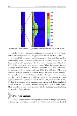
Figure 2.45 Distribution of CO 2oil in a field-scale model at the end of huff period.
respectively. The predicted gas penetration depth is shown in Fig. 2.46.At the
end of 100-day injection, the CO 2 penetrates 105.6 ft (Li et al., 2018).
Li et al. (2018) did more sensitivities using the field-scale base model.
Interestingly, when the matrix permeability is increased from 300 nD to
3000 nD, the CO 2 penetration depth is only increased from 105.6 ft to
106.5 ft. Fractures play a very important role. When the induced fracture
spacing is increased from 0.77 ft in the base model to 7.7 ft to no fracture,
the penetration depth is decreased from 105.6 ft to 68.7 ft to 0.31 ft. It is
expected that gas diffusion coefficient in the oil phase is very sensitive.
However, Sorensen et al. (2018) estimated that the CO 2 penetration radius
may be 50-70 ft around the wellbore based on the amount of CO 2
injected, the matrix porosity of 0.06-0.08 and CO 2 saturation of 0.4-0.6,
for their field injection test in an unfractured vertical well. Their simulation
model estimated a maximum penetration depth of 140 ft in some layers.
Their model was a dual-porosity model with the matrix permeability being
in the order of microdarcies.
2.15 Field projects
Table 2.4 summarizes the field projects for huff-n-puff gas injection in
shale and tight reservoirs published so far. Field project with some detailed