
Page 65 - Enhanced Oil Recovery in Shale and Tight Reservoirs
P. 65
Huff-n-puff gas injection in oil reservoirs 53
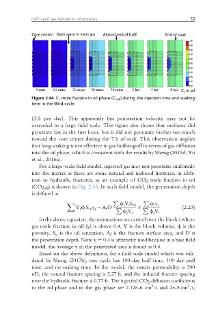
Figure 2.44 C 1 mole fraction in oil phase (C 1oil ) during the injection time and soaking
time in the third cycle.
(2 ft per day). This apparently fast penetration velocity may not be
extended to a large field scale. This figure also shows that methane did
penetrate fast in the first hour, but it did not penetrate further too much
toward the core center during the 7 h of soak. This observation implies
that long soaking is not effective in gas huff-n-puff in terms of gas diffusion
into the oil phase, which is consistent with the results by Sheng (2015d; Yu
et al., 2016a).
For a large-scale field model, injected gas may not penetrate uniformly
into the matrix as there are some natural and induced fractures, in addi-
tion to hydraulic fractures, as an example of CO 2 mole fraction in oil
(CO 2oil ) is shown in Fig. 2.45.Insuch field model, the penetration depth
is defined as
P P
f V i S oi i i
i
X f y
i
i
V i f S oi y ¼ A f D P P (2.23)
f V i f V i
i
i
In the above equation, the summations are carried over the block i where
gas mole fraction in oil (y) is above 0.4, V is the block volume, f is the
porosity, S o is the oil saturation, A f is the fracture surface area, and D is
the penetration depth. Note y ¼ 0.4 is arbitrarily used because in a base field
model, the average y in the penetrated area is found as 0.4.
Based on the above definitions, for a field-scale model which was vali-
dated by Sheng (2017b), one cycle has 100-day huff time, 100-day puff
time, and no soaking time. In the model, the matrix permeability is 300
nD, the natural fracture spacing is 2.27 ft, and the induced fracture spacing
near the hydraulic fracture is 0.77 ft. The injected CO 2 diffusion coefficients
2
2
in the oil phase and in the gas phase are 2.12e-6 cm /s and 2e-5 cm /s,