
Page 76 - Enhanced Oil Recovery in Shale and Tight Reservoirs
P. 76
Asphaltene precipitation and deposition in a huff-n-puff process 63
filtrate cylinder. The reservoir cylinder is a 400 mL stainless steel core holder
to store the dead crude oil and injected gas. Three stacks of nanomembranes
of 200, 100, and 30 nm were placed from the top to the bottom in the filter
cylinder, and they are supported by a stainless-steel frame. The filtrated
crude oil was deposited in the filtrate cylinder.
The apparatus was designed to study the effect of gas concentration on
asphaltene precipitation. For each test, 200 mL of oil was poured into the
reservoir cylinder. Then the gas cylinder was connected to the reservoir cyl-
inder, and the oil was saturated at a constant pressure. The pressure was
maintained for 8 h for equilibrium. The dissolved gas mole fraction at
each pressure was obtained from the gas solubility curve obtained prior to
the experiment. The filter cylinder and filtrate cylinder were precharged
with the gas at a pressure of 50 psi lower than that in the reservoir cylinder
using a back-pressure regulator to let the crude oil go through the mem-
branes. Then hot heptane was injected into the reservoir cylinder and forced
through the membranes to wash away the oil left in the membrane and in
the system, as asphaltene does not dissolve in heptane. This washing process
was continued until heptane collected from the outlet of filtrate cylinder was
clean. The amount of asphaltene precipitated on each membrane was
measured using a modified IP143 standard test method (Muhammad
et al., 2003).
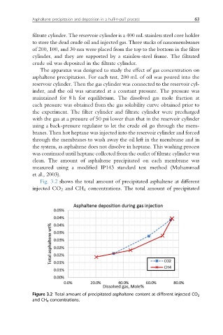
Fig. 3.2 shows the total amount of precipitated asphaltene at different
injected CO 2 and CH 4 concentrations. The total amount of precipitated
Figure 3.2 Total amount of precipitated asphaltene content at different injected CO 2
and CH 4 concentrations.