
Page 205 - Enhancing CAD Drawings with Photoshop
P. 205
4386.book Page 189 Monday, November 15, 2004 3:27 PM
LAYING OUT PLANS ON A SHEET 189
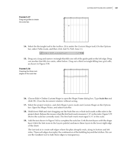
Figure 5.57
Drag out guides to create
the scale bar.
14. Select the Rectangle tool in the toolbox. (It is under the Custom Shape tool.) On the Options
bar, select Paths mode, and then click Add To Path Area (+).
15. Drag out a long and narrow rectangle that fills one cell of the guide grid on the left edge. Drag
out another that fills two units, offset below. Drag out a third rectangle filling four grid cells,
as shown in Figure 5.58.
Figure 5.58
Drawing the three rect-
angles of the scale bar
16. Choose Edit Define Custom Shape to open the Shape Name dialog box. Type Scale Bar and
click OK. Close the document window without saving.
17. Select the project window, and click Shape Layers mode and Custom Shape on the Options
bar. Open the Shape Picker, and select Scale Bar.
18. Hold down Shift and start dragging out the Scale Bar on a whole inch mark on the ruler in the
project sheet. Release the mouse when the first hash mark measures 1/4˝ on the ruler. Figure 5.59
shows the scale bar correctly sized. The first hash mark must equal 1/4˝ at this scale.
19. Add the text shown in Figure 5.60 to complete the scale bar. Link the text layers with the shape
layer (click the link icons in the Layers palette) and move these layers to the lower-right edge
of the sheet.
The last task is to create soft edges where the plan abruptly ends, along its bottom and left
sides. These soft edges downplay the continuation of the building beyond the kitchen. We can
use the Gradient tool to fade these edges to transparency.