
Page 111 - Entrophy Analysis in Thermal Engineering Systems
P. 111
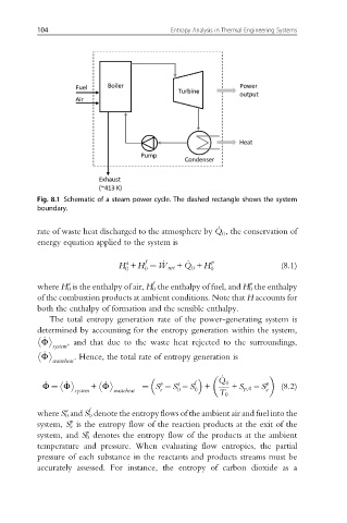
104                              Entropy Analysis in Thermal Engineering Systems


          Fig. 8.1 Schematic of a steam power cycle. The dashed rectangle shows the system
          boundary.

                                                       _
          rate of waste heat discharged to the atmosphere by Q , the conservation of
                                                        0
          energy equation applied to the system is
                                                _
                                     f               p
                                a                                      (8.1)
                                                 0
                                0
                                     0
                              H + H ¼ _ W net + Q + H 0
          where H 0 is the enthalpy of air, H 0 the enthalpy of fuel, and H 0 the enthalpy
                                       f
                                                               p
                  a
          of the combustion products at ambient conditions. Note that H accounts for
          both the enthalpy of formation and the sensible enthalpy.
             The total entropy generation rate of the power-generating system is
          determined by accounting for the entropy generation within the system,
           Φ      , and that due to the waste heat rejected to the surroundings,
            _

              system
            _
           Φ       . Hence, the total rate of entropy generation is

              wasteheat
                                                        _


                           _
            _
                 _
            Φ ¼ Φ       + Φ              p   a   f  +  Q 0         p   (8.2)


                                    ¼ S  S  S
                                         e   0   0         + S p,0  S e
                                                       T 0
                    system   wasteheat
          where S 0 and S 0 denote the entropy flows of the ambient air and fuel into the
                 a
                       f
          system, S e is the entropy flow of the reaction products at the exit of the
                  p
          system, and S 0 denotes the entropy flow of the products at the ambient
                      p
          temperature and pressure. When evaluating flow entropies, the partial
          pressure of each substance in the reactants and products streams must be
          accurately assessed. For instance, the entropy of carbon dioxide as a