
Page 117 - Entrophy Analysis in Thermal Engineering Systems
P. 117
110 Entropy Analysis in Thermal Engineering Systems
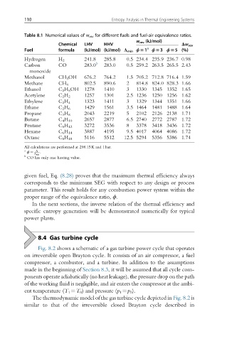
Table 8.1 Numerical values of w rev for different fuels and fuel-air equivalence ratios.
w rev (kJ/mol)
Chemical LHV HHV Δw rev
Fuel formula (kJ/mol) (kJ/mol) Λ min ϕ51 a ϕ53 ϕ55 (%)
Hydrogen H 2 241.8 285.8 0.5 234.4 235.9 236.7 0.98
Carbon CO 283.0 b 283.0 0.5 259.2 263.5 265.5 2.43
monoxide
Methanol CH 3 OH 676.2 764.2 1.5 705.2 712.8 716.4 1.59
Methane CH 4 802.5 890.6 2 814.8 824.0 828.3 1.66
Ethanol C 2 H 5 OH 1278 1410 3 1330 1345 1352 1.65
Acetylene C 2 H 2 1257 1301 2.5 1236 1250 1256 1.62
Ethylene C 2 H 4 1323 1411 3 1329 1344 1351 1.66
Ethane C 2 H 6 1429 1561 3.5 1464 1481 1488 1.64
Propane C 3 H 8 2043 2219 5 2102 2126 2138 1.71
Butane C 4 H 10 2657 2877 6.5 2740 2772 2787 1.72
Pentane C 5 H 12 3272 3536 8 3378 3418 3436 1.72
Hexane C 6 H 14 3887 4195 9.5 4017 4064 4086 1.72
Octane C 8 H 18 5116 5512 12.5 5294 5356 5386 1.74
All calculations are performed at 298.15K and 1bar.
a Λ :
ϕ ¼
b Λ min
CO has only one heating value.
given fuel, Eq. (8.28) proves that the maximum thermal efficiency always
corresponds to the minimum SEG with respect to any design or process
parameter. This result holds for any combustion power system within the
proper range of the equivalence ratio, ϕ.
In the next sections, the inverse relation of the thermal efficiency and
specific entropy generation will be demonstrated numerically for typical
power plants.
8.4 Gas turbine cycle
Fig. 8.2 shows a schematic of a gas turbine power cycle that operates
on irreversible open Brayton cycle. It consists of an air compressor, a fuel
compressor, a combustor, and a turbine. In addition to the assumptions
made in the beginning of Section 8.3, it will be assumed that all cycle com-
ponents operate adiabatically (no heat leakage), the pressure drop on the path
of the working fluid is negligible, and air enters the compressor at the ambi-
ent temperature (T 1 ¼T 0 ) and pressure (p 1 ¼p 0 ).
The thermodynamic model of the gas turbine cycle depicted in Fig. 8.2 is
similar to that of the irreversible closed Brayton cycle described in