
Page 118 - Entrophy Analysis in Thermal Engineering Systems
P. 118
Irreversible engines—Open cycles 111
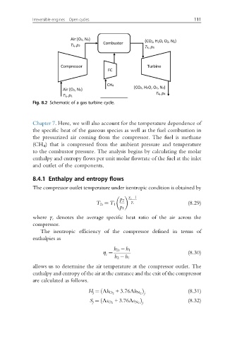
Fig. 8.2 Schematic of a gas turbine cycle.
Chapter 7. Here, we will also account for the temperature dependence of
the specific heat of the gaseous species as well as the fuel combustion in
the pressurized air coming from the compressor. The fuel is methane
(CH 4 ) that is compressed from the ambient pressure and temperature
to the combustor pressure. The analysis begins by calculating the molar
enthalpy and entropy flows per unit molar flowrate of the fuel at the inlet
and outlet of the components.
8.4.1 Enthalpy and entropy flows
The compressor outlet temperature under isentropic condition is obtained by
γ c 1
p 2
T 2s ¼ T 1 γ c (8.29)
p 1
where γ c denotes the average specific heat ratio of the air across the
compressor.
The isentropic efficiency of the compressor defined in terms of
enthalpies as
h 2s h 1
η ¼ (8.30)
c
h 2 h 1
allows us to determine the air temperature at the compressor outlet. The
enthalpy and entropy of the air at the entrance and the exit of the compressor
are calculated as follows.
ð Þ (8.31)
H j ¼ Λh O 2 +3:76Λh N 2 j
ð Þ (8.32)
S j ¼ Λs O 2 +3:76Λs N 2 j