
Page 120 - Entrophy Analysis in Thermal Engineering Systems
P. 120
Irreversible engines—Open cycles 113
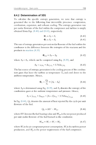
8.4.2 Determination of SEG
To calculate the specific entropy generation, we note that entropy is
generated due to the following four irreversible processes: compression,
combustion, expansion, and exhaust cooling. The entropy generation rate
per molar flowrate of the fuel within the compressor and turbine is simply
obtained from Eqs. (8.40) and (8.41), respectively.
(8.40)
Φ c ¼ S 2 S 1
(8.41)
Φ t ¼ S 4 S 3
The rate of entropy generation per unit molar flowrate of the fuel within the
combustor is the difference between the entropies of the reactants and the
products in reaction (8.33)
(8.42)
Φ com ¼ S P S R
where S P ¼S 3 , which can be computed using Eq. (8.39), and
(8.43)
S R ¼ s CH 4 + Λs 2,O 2 +3:76Λs 2,N 2
The last source of entropy generation is the cooling process of the combus-
tion gases that leave the turbine at temperature T 4 and cool down to the
ambient temperature. Hence,
Φ L ¼ Q L + S 5 S 4 Þ (8.44)
ð
T 0
where S 4 is determined using Eq. (8.39), and S 5 denotes the entropy of the
combustion gases at the ambient temperature and pressure. Hence,
½ ð (8.45)
S 5 ¼ s CO 2 +2s H 2 O + Λ 2Þs O 2 +3:76Λs N 2 T 0 ,p 0
In Eq. (8.44), Q L denotes the amount of heat rejected by the cycle per unit
flowrate of the fuel.
(8.46)
Q L ¼ HV W net
where HV denotes the fuel heating value and W net is the net power produced
per unit molar flowrate of the fuel burned in the combustor.
(8.47)
W net ¼ W t W c W fc
where W c is the air compressor power consumption, W t is the turbine power
production, and W fc is the power requirement of the fuel compressor.