
Page 123 - Entrophy Analysis in Thermal Engineering Systems
P. 123
116 Entropy Analysis in Thermal Engineering Systems
8.5 Regenerative gas turbine cycle
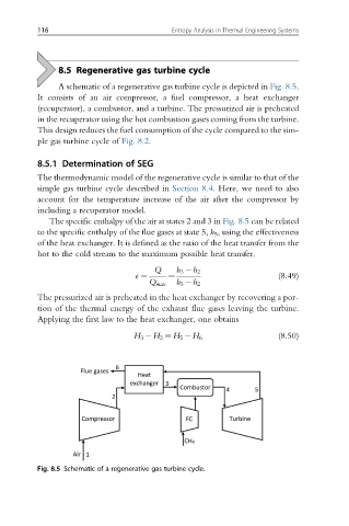
A schematic of a regenerative gas turbine cycle is depicted in Fig. 8.5.
It consists of an air compressor, a fuel compressor, a heat exchanger
(recuperator), a combustor, and a turbine. The pressurized air is preheated
in the recuperator using the hot combustion gases coming from the turbine.
This design reduces the fuel consumption of the cycle compared to the sim-
ple gas turbine cycle of Fig. 8.2.
8.5.1 Determination of SEG
The thermodynamic model of the regenerative cycle is similar to that of the
simple gas turbine cycle described in Section 8.4. Here, we need to also
account for the temperature increase of the air after the compressor by
including a recuperator model.
The specific enthalpy of the air at states 2 and 3 in Fig. 8.5 can be related
to the specific enthalpy of the flue gases at state 5, h 5 , using the effectiveness
of the heat exchanger. It is defined as the ratio of the heat transfer from the
hot to the cold stream to the maximum possible heat transfer.
h 3 h 2
Q
E ¼ ¼ (8.49)
h 5 h 2
Q max
The pressurized air is preheated in the heat exchanger by recovering a por-
tion of the thermal energy of the exhaust flue gases leaving the turbine.
Applying the first law to the heat exchanger, one obtains
H 3 H 2 ¼ H 5 H 6 (8.50)
Fig. 8.5 Schematic of a regenerative gas turbine cycle.