
Page 128 - Entrophy Analysis in Thermal Engineering Systems
P. 128
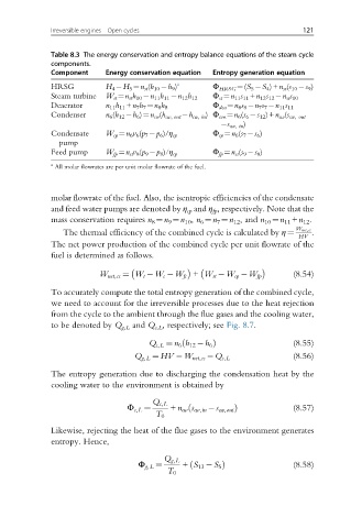
Irreversible engines—Open cycles                             121


              Table 8.3 The energy conservation and entropy balance equations of the steam cycle
              components.
              Component    Energy conservation equation  Entropy generation equation
                                             a
              HRSG         H 4  H 5 ¼n st (h 10  h 9 )  Φ HRSG ¼(S 5  S 4 )+n st (s 10  s 9 )
              Steam turbine  W st ¼n st h 10  n 11 h 11  n 12 h 12  Φ st ¼n 11 s 11 +n 12 s 12  n st s 10
              Deaerator    n 11 h 11 +n 7 h 7 ¼n 8 h 8  Φ dea ¼n 8 s 8  n 7 s 7  n 11 s 11
              Condenser    n 6 (h 12  h 6 )¼n cw (h cw, out  h cw, in ) Φ con ¼n 6 (s 6  s 12 )+n cw (s cw, out
                                                        s cw, in )
              Condensate   W cp ¼n 6 v 6 (p 7  p 6 )/η cp  Φ cp ¼n 6 (s 7  s 6 )
                pump
              Feed pump    W fp ¼n st v 8 (p 9  p 8 )/η cp  Φ fp ¼n st (s 9  s 8 )
              a
               All molar flowrates are per unit molar flowrate of the fuel.


              molar flowrate of the fuel. Also, the isentropic efficiencies of the condensate
              and feed water pumps are denoted by η cp and η fp , respectively. Note that the
              mass conservation requires n 8 ¼n 9 ¼n 10 , n 6 ¼n 7 ¼n 12 , and n 10 ¼n 11 +n 12 .

                 The thermal efficiency of the combined cycle is calculated by η ¼  W net,cc .
                                                                          HV
              The net power production of the combined cycle per unit flowrate of the
              fuel is determined as follows.

                                                                         (8.54)
                         W net,cc ¼ W t  W c  W fc + W st  W cp  W fp
              To accurately compute the total entropy generation of the combined cycle,
              we need to account for the irreversible processes due to the heat rejection
              from the cycle to the ambient through the flue gases and the cooling water,
              to be denoted by Q g,L and Q c,L , respectively; see Fig. 8.7.

                                      Q c,L ¼ n 6 h 12  h 6 Þ            (8.55)
                                              ð
                                                                         (8.56)
                                  Q g,L ¼ HV  W net,cc  Q c,L
              The entropy generation due to discharging the condensation heat by the
              cooling water to the environment is obtained by


                                Φ c,L ¼  Q c,L  + n cw s cw,in  s cw,out Þ  (8.57)
                                               ð
                                       T 0
              Likewise, rejecting the heat of the flue gases to the environment generates
              entropy. Hence,


                                   Φ g,L ¼  Q g,L  + S 13  S 5 Þ         (8.58)
                                                ð
                                          T 0