
Page 126 - Entrophy Analysis in Thermal Engineering Systems
P. 126
Irreversible engines—Open cycles 119
the increased share of the recuperator as E increases. Thus, a higher E leads to
a lower SEG and a higher efficiency, which was also noted in Table 8.2.
8.6 Combined cycle
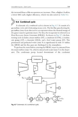
A schematic of a combined cycle is shown in Fig. 8.7. It consists of a
gas turbine cycle and a bottoming steam cycle. The hot flue gases leaving the
gas turbine (state 4) are directed to a recuperator where the thermal energy of
the gases is used to generate steam. For this, the recuperator is referred to as
Heat Recovery Steam Generator (HRSG). As shown in Fig. 8.7, the bot-
toming cycle includes a steam turbine (ST), a condenser (CON), a conden-
sate pump (CP), a deaerator (DEA), and a feed water pump (FP). The
pressurized and preheated water (state 9) is superheated to state 10 within
the HRSG and the flue gases are discharged to the atmosphere.
To preheat the water before entering the HRSG, steam is extracted from
the steam turbine (state 11), which is mixed with water (state 7) in the deaer-
ator. The condensate pump located downstream of the condenser
Fig. 8.7 Schematic of a combined cycle.