
Page 127 - Entrophy Analysis in Thermal Engineering Systems
P. 127
120 Entropy Analysis in Thermal Engineering Systems
pressurizes the condensate to the steam extraction pressure, i.e., p 7 ¼p 11 .
The feed water pump further increases the pressure of the preheated water
leaving the deaerator to a desired pressure p 9 . The saturated steam leaving the
steam turbine (state 12) is condensed at a subatmospheric pressure within the
condenser. The condensation heat is then transferred to the cooling water
(CW), which is cooled down to a desired temperature and recirculated back
to the condenser. In fact, the cooling water is a medium between the con-
denser and the ambient. It first absorbs the condensation heat and then
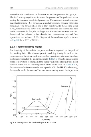
rejects it to the ambient. A T-s diagram of the combined cycle is shown
in Fig. 8.8 for a TIT of 1273K.
8.6.1 Thermodynamic model
For simplicity of the analysis, the pressure drop is neglected on the path of
the working fluid. The thermodynamic modeling is only focused on the
components of the steam cycle since we have previously discussed the ther-
modynamic model of the gas turbine cycle. Table 8.3 provides the equations
of the conservation of energy and the entropy generation rate per unit molar
flowrate of the fuel for the components of the steam cycle. In Table 8.3, n st
denotes the molar flowrate of the steam produced in the HRSG, whereas n cw
denotes the molar flowrate of the condenser cooling water, both per unit
Fig. 8.8 T-s diagram of the combined cycle at TIT¼1273K.