
Page 41 - Entrophy Analysis in Thermal Engineering Systems
P. 41
32 Entropy Analysis in Thermal Engineering Systems
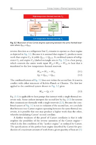
High-temperature thermal reservoir, T H
Q HC1 Q HC2
C 1 C 2
W
Carnot Carnot net
refrigerator engine
Q LC1 Q LC2
Low-temperature thermal reservoir, T L
Fig. 3.2 Illustration of two Carnot engines operating between the same thermal reser-
voirs where Q HC1 ¼Q HC2 .
reverse direction as a refrigerator but C 2 remains to operate as a heat engine
as depicted in Fig. 3.2. Because it is assumed that engine C 1 produces more
work than engine C 2 , it yields Q LC1 <Q LC2 . A combined system of refrig-
erator C 1 and engine C 2 (dashed rectangle area in Fig. 3.2) is a heat pump,
which converts the entire work input W net ¼W C1 W C2 to heat that is
transferred to the low-temperature thermal reservoir.
(3.1)
W net ¼ W C 1 W C 2
(3.2)
Q L ¼ Q LC 2 Q LC 1
The combined system of Fig. 3.2 does not violate the second law. It is not in
conflict with either statement of Kelvin-Planck or Clausius. The first law
applied to the combined system shown in Fig. 3.2 gives
W net ¼ Q L < 0 (3.3)
Eq. (3.3) is applicable to heat pumps that interact with a single thermal res-
ervoir only. Some authors interpret the second law by Eq. (3.3) for systems
that communicate thermally with a single reservoir [2,3]. Because the com-
bined system of Fig. 3.2 is not in violation of the second law, we conclude
that between two Carnot engines operating between the same thermal res-
ervoirs, it is possible that one may produce a higher work than the other,
whereby invalidating Carnot’ second corollary.
A further weakness of the proof of Carnot corollaries is that it only
employs the possibility of the reverse operation of the Carnot engine—
which is the first condition of the “perfect engine” as outlined by Carnot.
The specifications of the perfect heat engine described by Carnot for pro-
duction of a maximum amount of work from a given quantity of heat are [1]: