Page 70 - Entrophy Analysis in Thermal Engineering Systems
P. 70

62                               Entropy Analysis in Thermal Engineering Systems


          2!3, adiabatic expansion 3!4, and isochoric heat removal. For this cycle,
          we have p 2 ¼p 3 , V 4 ¼V 1 , CR¼V 1 /V 2 , PR¼p 2 /p 1 , and T R ¼T 3 /T 1 . The
          thermal efficiency of the cycle can be described as


                                         1    T 4 =T 1  1
                                 q 41
                          η ¼ 1     ¼ 1                               (5.24)
                                 q 23    γ T 3 =T 1  T 2 =T 1
          For the adiabatic processes 1!2 and 3!4, we have
                                          1 γ

                                T 2   V 2         γ 1
                                   ¼         ¼ CR                     (5.25)
                                T 1   V 1
                                 1 γ           1 γ       γ    1 γ
                       T 4   V 4        V 1 T 2       CR
                         ¼          ¼             ¼                   (5.26)
                       T 3   V 3        V 2 T 3       T R
          Note that Eq. (5.25) and the relation V 3 /V 2 ¼T 3 /T 2 are used in Eq. (5.26).
          The thermal efficiency of the Diesel cycle can now be obtained in terms of
          T R and CR using Eqs. (5.25) and (5.26) in Eq. (5.24). Hence,
                                         γ    γ 1 γ
                                      "               #
                                     1 T CR Þ       1
                                          ð
                              η ¼ 1      R                            (5.27)
                                     γ   T R  CR γ 1
                                                                         1
                                                                         γ
          Like the Atkinson cycle, the relation between CR and PR obeys CR ¼ PR .
          5.2.6 Miller cycle

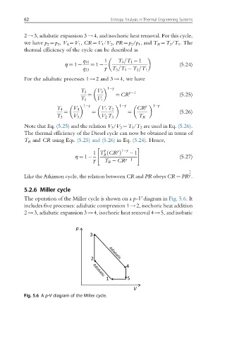
          The operation of the Miller cycle is shown on a p-V diagram in Fig. 5.6.It
          includes five processes: adiabatic compression 1!2, isochoric heat addition
          2!3, adiabatic expansion 3!4, isochoric heat removal 4!5, and isobaric


          Fig. 5.6 A p-V diagram of the Miller cycle.
   65   66   67   68   69   70   71   72   73   74   75