Page 122 - Facility Piping Systems Handbook for Industrial, Commercial, and Healthcare Facilities
P. 122

PIPING

                      2.72                       CHAPTER TWO


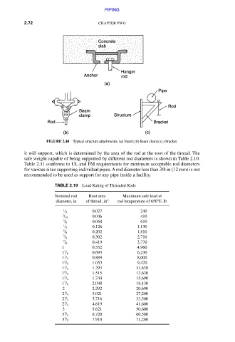
                              FIGURE 2.40  Typical structure attachments. (a) Insert; (b) beam clamp; (c) bracket.

                      it will support, which is determined by the area of the rod at the root of the thread. The
                      safe weight capable of being supported by different rod diameters is shown in Table 2.10.
                      Table 2.11 conforms to UL and FM requirements for minimum acceptable rod diameters
                      for various sizes supporting individual pipes. A rod diameter less than 3/8 in (12 mm) is not
                      recommended to be used as support for any pipe inside a facility.

                                 TABLE 2.10  Load Rating of Threaded Rods
                                   Nominal rod    Root area    Maximum safe load at
                                  diameter, in   of thread, in 2   rod temperature of 650°F, lb
                                    1          0.027              240
                                    / 4
                                    5          0.046              410
                                    / 16
                                    3          0.068              610
                                    / 8
                                    1          0.126           1,130
                                    / 2
                                    5          0.202           1,810
                                    / 8
                                    3          0.302           2,710
                                    / 4
                                    7          0.419           3,770
                                    / 8

                                   1           0.552           4,960
                                    1          0.693           6,230
                                    1 / 8
                                    1
                                    1 / 4      0.889           8,000
                                    3          1.053           9,470
                                    1 / 8
                                    1
                                    1 / 2      1.293           11,630
                                    5          1.515           13,630
                                    1 / 8
                                    3
                                    1 / 4      1.744           15,690
                                    7          2.048           18,430
                                    1 / 8

                                    2          2.292           20,690
                                    1          3.021           27,200
                                    2 / 4
                                    1
                                    2 / 2      3.716           33,500
                                    3          4.619           41,600
                                    2 / 4

                                    3          5.621           50,600
                                    1          6.720           60,500
                                    3 / 4
                                    1
                                    3 / 2      7.918           71,260

                   Downloaded from Digital Engineering Library @ McGraw-Hill (www.accessengineeringlibrary.com)
                              Copyright © 2009 The McGraw-Hill Companies. All rights reserved.
                                Any use is subject to the Terms of Use as given at the website.
   117   118   119   120   121   122   123   124   125   126   127