
Page 123 - Facility Piping Systems Handbook for Industrial, Commercial, and Healthcare Facilities
P. 123
PIPING
PIPING 2.73
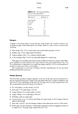
TABLE 2.11 Recommended Rod
Size for Individual Pipes
Pipe size, in Rod size, in
2 and smaller 3 / 8
1 1 1
2 / 2 to 2 / 2 / 2
4 and 5 5 / 8
6 3 / 4
8 to 12 7 / 8
14 and 16 1
1
18 1 / 8
1
20 1 / 4
1
24 1 / 2
Hangers
A hanger is the device used to secure the pipe to the hanger rod. It must not distort, cut,
or abrade any pipe while allowing free movement. There is a wide variety to choose from,
including:
1. Pipe clamps (Fig. 2.41a) support pipes passing through openings in floors.
2. Saddles (Fig. 2.41b) support pipe from floors.
3. Trapeze hangers (Fig. 2.41c) support multiple pipes.
4. A clevis hanger (Fig. 2.41d) is an adjustable hanger for a single pipe.
When pipes are insulated, precautions must be taken in order not to distort softer fiber-
glass insulation or create a break in the vapor barrier, if one is provided. Refer to Fig. 2.42
for an illustration of insulation over a split ring hanger and Fig. 2.43 for an illustration of
protective inserts used with a clevis hanger.
The manufacturer of each type of hanger will have specifications for the maximum
loading permitted for each type.
Hanger Spacing
The horizontal spacing of hangers depends on the size of the pipe and the requirement to
prevent sagging based on the weight of the pipe filled with water, weight of insulation, and
other heavy valves and fittings on the pipe run. For pipe where no other requirements exist,
the recommended maximum spacing is as follows:
1. For steel piping 1 in and smaller, 8 ft O.C.
2. Steel pipe 1 1/4 in and larger, 12 ft OC.
3. Copper tubing 1 1/4 in and smaller, 6 ft O.C.
4. Copper tubing 1 1/2 in and larger, 10 ft O.C.
5. SS tubing, same as copper pipe.
6. Cast iron pipe, every 5 ft and at each fitting. For pipe length of 10 ft, hangers shall be
equal to pipe length.
7. Glass pipe, 10 ft O.C. and extra hangers at places where three joints exist in a 10-ft section.
8. Plastic pipe-all sizes and types, continuously supported to prevent sagging by means of
an angle iron or 18-gauge angle, supported every 10 ft.
Downloaded from Digital Engineering Library @ McGraw-Hill (www.accessengineeringlibrary.com)
Copyright © 2009 The McGraw-Hill Companies. All rights reserved.
Any use is subject to the Terms of Use as given at the website.