
Page 156 - Facility Piping Systems Handbook for Industrial, Commercial, and Healthcare Facilities
P. 156
SOLID-LIQUID SEPARATION AND INTERCEPTORS
3.24 CHAPTER THREE
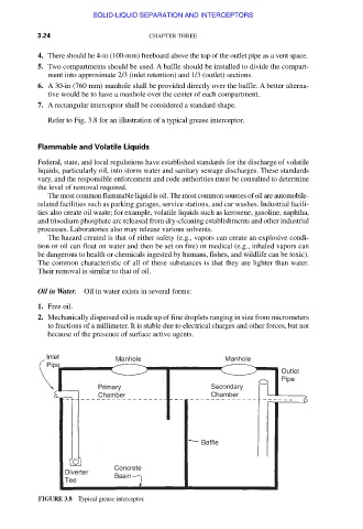
4. There should be 4-in (100-mm) freeboard above the top of the outlet pipe as a vent space.
5. Two compartments should be used. A baffle should be installed to divide the compart-
ment into approximate 2/3 (inlet retention) and 1/3 (outlet) sections.
6. A 30-in (760 mm) manhole shall be provided directly over the baffle. A better alterna-
tive would be to have a manhole over the center of each compartment.
7. A rectangular interceptor shall be considered a standard shape.
Refer to Fig. 3.8 for an illustration of a typical grease interceptor.
Flammable and Volatile Liquids
Federal, state, and local regulations have established standards for the discharge of volatile
liquids, particularly oil, into storm water and sanitary sewage discharges. These standards
vary, and the responsible enforcement and code authorities must be consulted to determine
the level of removal required.
The most common flammable liquid is oil. The most common sources of oil are automobile-
related facilities such as parking garages, service stations, and car washes. Industrial facili-
ties also create oil waste; for example, volatile liquids such as kerosene, gasoline, naphtha,
and trisodium phosphate are released from dry-cleaning establishments and other industrial
processes. Laboratories also may release various solvents.
The hazard created is that of either safety (e.g., vapors can create an explosive condi-
tion or oil can float on water and then be set on fire) or medical (e.g., inhaled vapors can
be dangerous to health or chemicals ingested by humans, fishes, and wildlife can be toxic).
The common characteristic of all of these substances is that they are lighter than water.
Their removal is similar to that of oil.
Oil in Water. Oil in water exists in several forms:
1. Free oil.
2. Mechanically dispersed oil is made up of fine droplets ranging in size from micrometers
to fractions of a millimeter. It is stable due to electrical charges and other forces, but not
because of the presence of surface active agents.
Inlet Manhole Manhole
Pipe
Outlet
Pipe
Primary Secondary
Chamber Chamber
Baffle
Concrete
Diverter Basin
Tee
FIGURE 3.8 Typical grease interceptor.
Downloaded from Digital Engineering Library @ McGraw-Hill (www.accessengineeringlibrary.com)
Copyright © 2009 The McGraw-Hill Companies. All rights reserved.
Any use is subject to the Terms of Use as given at the website.