
Page 197 - Facility Piping Systems Handbook for Industrial, Commercial, and Healthcare Facilities
P. 197
WATER TREATMENT AND PURIFICATION
WATER TREATMENT AND PURIFICATION 4.33
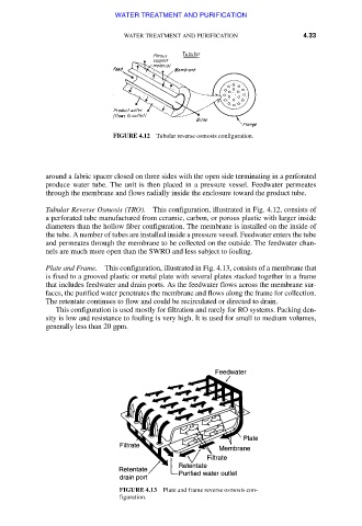
FIGURE 4.12 Tubular reverse osmosis configuration.
around a fabric spacer closed on three sides with the open side terminating in a perforated
produce water tube. The unit is then placed in a pressure vessel. Feedwater permeates
through the membrane and flows radially inside the enclosure toward the product tube.
Tubular Reverse Osmosis (TRO). This configuration, illustrated in Fig. 4.12, consists of
a perforated tube manufactured from ceramic, carbon, or porous plastic with larger inside
diameters than the hollow fiber configuration. The membrane is installed on the inside of
the tube. A number of tubes are installed inside a pressure vessel. Feedwater enters the tube
and permeates through the membrane to be collected on the outside. The feedwater chan-
nels are much more open than the SWRO and less subject to fouling.
Plate and Frame. This configuration, illustrated in Fig. 4.13, consists of a membrane that
is fixed to a grooved plastic or metal plate with several plates stacked together in a frame
that includes feedwater and drain ports. As the feedwater flows across the membrane sur-
faces, the purified water penetrates the membrane and flows along the frame for collection.
The retentate continues to flow and could be recirculated or directed to drain.
This configuration is used mostly for filtration and rarely for RO systems. Packing den-
sity is low and resistance to fouling is very high. It is used for small to medium volumes,
generally less than 20 gpm.
FIGURE 4.13 Plate and frame reverse osmosis con-
figuration.
Downloaded from Digital Engineering Library @ McGraw-Hill (www.accessengineeringlibrary.com)
Copyright © 2009 The McGraw-Hill Companies. All rights reserved.
Any use is subject to the Terms of Use as given at the website.