
Page 230 - Facility Piping Systems Handbook for Industrial, Commercial, and Healthcare Facilities
P. 230
HEAT TRANSFER, INSULATION, AND FREEZE PROTECTION
5.14 CHAPTER FIVE
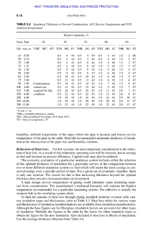
TABLE 5.2 Insulation Thickness to Prevent Condensation, 34°F Service Temperature and 70°F
Ambient Temperature *
Relative humidity, %
Nom. Pipe 20 50 70 80 90
DN size, in TNK † HC ‡ ST § THK HG ST THK HG ST THK HG ST THK HG ST
15 0.50 0.5 4 64 0.5 4 64 0.5 4 64 1.5 2 68
20 0.75 0.5 4 64 0.5 4 64 0.5 4 64 1.5 3 67
25 1.00 0.5 6 63 0.5 6 63 1.0 4 66 1.5 3 67
32 1.25 0.5 6 63 0.5 6 63 1.0 5 65 1.5 3 67
40 1.50 0.5 8 62 0.5 8 62 1.0 5 66 1.5 4 67
50 2.00 0.5 8 63 0.5 6 63 1.0 6 66 1.5 4 67
65 2.50 0.5 10 63 0.5 10 63 1.0 6 66 1.5 5 67
75 3.00 0.5 12 62 0.5 12 62 1.0 8 65 1.5 6 67
90 3.50 Condensation 0.5 14 61 0.5 14 61 1.0 7 66 1.5 6 67
100 4.00 control not 0.5 15 62 0.5 15 62 1.0 9 65 1.5 7 67
125 5.00 required for this 0.5 16 63 0.5 16 63 1.0 11 65 2.0 7 67
150 6.00 condition 0.5 22 61 0.5 22 61 1.0 13 65 2.0 8 67
200 8.00 1.0 16 65 1.0 16 65 1.0 16 65 2.0 10 67
250 10.00 1.0 20 65 1.0 20 65 1.0 20 65 2.0 11 67
300 12.00 1.0 22 65 1.0 22 65 1.0 22 65 2.0 13 67
* 25 mm = 1 in.
† THK = Insulation thickness, inches.
‡ HG = Heat gain/lineal foot (pipe) 28 ft (flat), BTU.
§ ST = Surface temperature, °F.
humidity, ambient temperature of the space where the pipe is located, and lowest service
temperature of the pipe in the table. Read the recommended minimum thickness of insula-
tion at the intersection of the pipe size and humidity columns.
Reduction of Heat Loss. For hot systems, the most important consideration is the reduc-
tion of heat loss. As a result of this reduction, operating cost will be lowered, due to savings
in fuel and increase in process efficiency. Capital costs may also be reduced.
The economic evaluation of a particular insulation system includes either the selection
of the optimal thickness of insulation for a particular service or the comparison between
two or more different insulation systems to find which will return the most savings in con-
served energy over a specific period of time. For a given set of economic variables, there
is only one solution. The reason for this is that increasing thickness beyond the optimal
thickness does not give increased return on investment.
A high design service temperature of piping could eliminate some insulating mate-
rial from consideration. The manufacturer’s technical literature will indicate the highest
temperature recommended for a particular insulating system. The adhesive is usually the
weakest link in the insulating system chain.
To find the amount of heat lost through piping installed outdoors covered with vari-
ous insulation types and thicknesses, refer to Table 5.3. Heat loss tables for various types
and thicknesses of insulation installed indoors are available from insulation manufacturers.
Although the base figures are for fiberglass, insulation factors are provided for other types
of insulation. Multiply the figures in the table by the factor for other insulation types to
obtain the figure for the new insulation. Also included is heat loss in Btu/in of insulation.
Use the average thickness obtained from Table 5.6.
Downloaded from Digital Engineering Library @ McGraw-Hill (www.accessengineeringlibrary.com)
Copyright © 2009 The McGraw-Hill Companies. All rights reserved.
Any use is subject to the Terms of Use as given at the website.