
Page 234 - Facility Piping Systems Handbook for Industrial, Commercial, and Healthcare Facilities
P. 234
HEAT TRANSFER, INSULATION, AND FREEZE PROTECTION
5.18 CHAPTER FIVE
provide criteria for the specific conditions that may be present in the design of a specific
project. It is for these circumstances that the formulas will be used. Before proceeding with
actual calculations, the following paragraphs will describe several typical factors and basic
formulas from which the design criteria are derived.
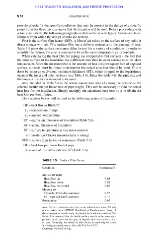
First is the surface film factor (SFF). A film of air exists on the surface of any solid in
direct contact with air. This surface film has a definite resistance to the passage of heat.
Table 5.5 gives the surface resistance (film factor) for a variety of conditions. In order to
simplify the figures, the pipe is assumed to be at the same temperature as its contents.
When calculating the heat flux for piping (as compared to flat surfaces), the fact that
the inner surface of the insulation has a different area than its outer surface must be taken
into account. Since the measurement is the amount of heat loss per square foot of exposed
surface, a means must be found to determine the actual area that should be used. This is
done by using an equivalent insulation thickness (ET), which is equal to the logarithmic
mean of the inner and outer surfaces (see Table 5.6). Enter this table with the pipe size and
thickness of insulation intended to be used.
Also included in Table 5.6 is the actual square foot area (A) along the outside of the
selected insulation per linear foot of pipe length. This will be necessary to find the actual
heat loss for the installation. Simply multiply the calculated heat loss by A to obtain the
heat loss per foot of pipe.
The variables below will be used in the following series of formulas:
HF = heat flux in Btu/h/ft 2
T = temperature of pipe
1
T = ambient temperature
2
ET = equivalent thickness of insulation (Table 5.6)
AT = actual thickness of insulation
ST = surface temperature at insulation exterior
k = insulation k factor (manufacturer’s rating)
SFR = surface film factor, or resistance (Table 5.5)
HL = heat loss per linear foot of pipe
2
A = area of insulation exterior, ft (Table 5.6)
TABLE 5.5 Surface Film Factor
Condition Resistance R
Still air (0 mph)
Heat flow up 0.61
Heat flow down 0.92
Heat flow horizontal 0.68
Moving air
7.5 mph (12 km/h) (summer) 0.25
15.0 mph (24 km/h) (winter) 0.17
Round pipe 0.65
Note: Surface resistances decrease as air velocities increase. All val-
ues are taken from ASHRAE Handbook of Fundamentals. Some of
these examples consider only the insulation surface-to-ambient film
factor. It is assumed that the inside surface area is at the same tem-
perature as the contents (air, gas, or liquid), such as in a duct, pipe,
or tank. Generally, the inside air film factor is used only for cases
involving occupied spaces, 60 to 90°F (15 to 32°C).
Courtesy: Owens/Corning.
Downloaded from Digital Engineering Library @ McGraw-Hill (www.accessengineeringlibrary.com)
Copyright © 2009 The McGraw-Hill Companies. All rights reserved.
Any use is subject to the Terms of Use as given at the website.