
Page 257 - Facility Piping Systems Handbook for Industrial, Commercial, and Healthcare Facilities
P. 257
HEAT TRANSFER, INSULATION, AND FREEZE PROTECTION
HEAT TRANSFER, INSULATION, AND FREEZE PROTECTION 5.41
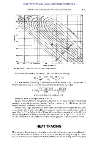
FIGURE 5.15 Coefficient in the modified Berrigan formula.
To find the thermal ratio [TR in Eq. (5.13)] calculate the following:
TR = ST = (43 .7 − 32 ) = 11 .7 = . 109
AD 10 .7 10 .7
It is now possible to enter Fig. 5.13 with 0.14 and 1.09. Read C = 0.8. This gives us all
the information needed to solve the modified Berrigan formula, Eq. (5.12),
×
.
48 ×1 01 2150 104 232
.
X = 08 . = 08 .
2160 2160
×
= 08 . × 48..25 = . 08 694 = . 555 ft
.
Estimated depth of frost penetration is 5.55 ft.
Several nomographs have been prepared based on the modified Berrigan formula that
are easier to use than the original formula. The first is shown in Fig. 5.16, giving the frost
depth for various conditions as a direct reading.
In some cases, a pipe may have been buried under a road and a nonsusceptible fill used. This
means that the fill will not be affected by frost, and so the condition known as frost heave will not
occur. Use Fig. 5.17 to find the depth of fill that will prevent frost penetration below the fill. For a
direct reading of the actual frost penetration under pavements, refer to Figs. 5.18, 5.19, and 5.20.
Use the combination of soil weight and moisture content applicable to the project under design.
HEAT TRACING
Heat tracing is the continuous or intermittent application of heat to a pipe or vessel in order
to replace the heat lost to ambient air. Heat tracing is used for preventing freezing, for thaw-
ing, for maintaining the temperature of pipe contents, and for facilitating product transport
Downloaded from Digital Engineering Library @ McGraw-Hill (www.accessengineeringlibrary.com)
Copyright © 2009 The McGraw-Hill Companies. All rights reserved.
Any use is subject to the Terms of Use as given at the website.