
Page 276 - Facility Piping Systems Handbook for Industrial, Commercial, and Healthcare Facilities
P. 276
HEAT TRANSFER, INSULATION, AND FREEZE PROTECTION
5.60 CHAPTER FIVE
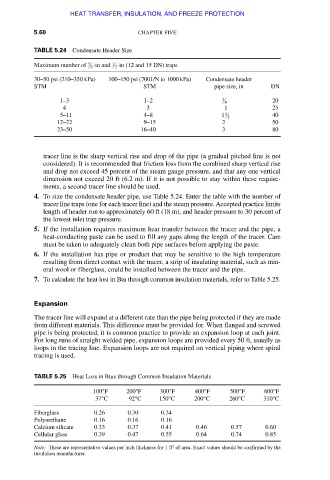
TABLE 5.24 Condensate Header Size
1
3
Maximum number of 8 -in and 2 -in (12 and 15 DN) traps
30–50 psi (210–350 kPa) 100–150 psi (7001/N to 1000 kPa) Condensate header
STM STM pipe size, in DN
1–3 1–2 3 4 20
4 3 1 25
1
5–11 4–8 1 2 40
12–22 9–15 2 50
23–50 16–40 3 80
tracer line is the sharp vertical rise and drop of the pipe (a gradual pitched line is not
considered). It is recommended that friction loss from the combined sharp vertical rise
and drop not exceed 45 percent of the steam gauge pressure, and that any one vertical
dimension not exceed 20 ft (6.2 m). If it is not possible to stay within these require-
ments, a second tracer line should be used.
4. To size the condensate header pipe, use Table 5.24. Enter the table with the number of
tracer line traps (one for each tracer line) and the steam pressure. Accepted practice limits
length of header run to approximately 60 ft (18 m), and header pressure to 30 percent of
the lowest inlet trap pressure.
5. If the installation requires maximum heat transfer between the tracer and the pipe, a
heat-conducting paste can be used to fill any gaps along the length of the tracer. Care
must be taken to adequately clean both pipe surfaces before applying the paste.
6. If the installation has pipe or product that may be sensitive to the high temperature
resulting from direct contact with the tracer, a strip of insulating material, such as min-
eral wool or fiberglass, could be installed between the tracer and the pipe.
7. To calculate the heat lost in Btu through common insulation materials, refer to Table 5.25.
Expansion
The tracer line will expand at a different rate than the pipe being protected if they are made
from different materials. This difference must be provided for. When flanged and screwed
pipe is being protected, it is common practice to provide an expansion loop at each joint.
For long runs of straight welded pipe, expansion loops are provided every 50 ft, usually as
loops in the tracing line. Expansion loops are not required on vertical piping where spiral
tracing is used.
TABLE 5.25 Heat Loss in Btus through Common Insulation Materials
100°F 200°F 300°F 400°F 500°F 600°F
37°C 92°C 150°C 200°C 260°C 310°C
Fiberglass 0.26 0.30 0.34
Polyurethane 0.16 0.16 0.16
Calcium silicate 0.33 0.37 0.41 0.46 0.57 0.60
Cellular glass 0.39 0.47 0.55 0.64 0.74 0.85
2
Note: These are representative values per inch thickness for 1 ft of area. Exact values should be confirmed by the
insulation manufacturer.
Downloaded from Digital Engineering Library @ McGraw-Hill (www.accessengineeringlibrary.com)
Copyright © 2009 The McGraw-Hill Companies. All rights reserved.
Any use is subject to the Terms of Use as given at the website.