
Page 273 - Facility Piping Systems Handbook for Industrial, Commercial, and Healthcare Facilities
P. 273
HEAT TRANSFER, INSULATION, AND FREEZE PROTECTION
HEAT TRANSFER, INSULATION, AND FREEZE PROTECTION 5.57
a steam trap, and a strainer with a blowdown valve should be installed before the steam trap
at the end of each tracing run.
When condensate is to be disposed of, a subcooling trap will enhance the energy effi-
ciency of a tracer system by allowing sensible heat to contribute to the heating duty. These
traps release condensate only after it has cooled well below the saturation temperature. Where
supply temperature control valves are used, the condensate traps at the end of the tracer run
will be in the closed position when the tracing duty is satisfied and the steam is shut off.
Since the pressure driving the condensate through the trap will be zero, it is important that the
selected trap not require pressure to operate. These traps are classified as free-draining, and
are known as temperature-sensing or thermostatic steam traps. The trap should be installed in
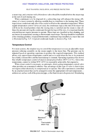
a free-draining position. A typical thermostatic condensate trap installed at a tracer line end
is illustrated in Fig. 5.27. A typical condensate header is shown in Fig. 5.28.
Temperature Control
For most systems, the simplest way to control the temperature is to use an adjustable steam
pressure reducing assembly on the steam supply to the tracer line. The pressure can be
adjusted based on operating experience to produce the required temperature. This method
allows only approximate temperature control and so is used when the line to be protected
has a fairly constant flow and the heat makeup is constant. Operating experience has shown
that reliable temperature control of steam is not practical below 250°F (121°C). Above this
temperature, control to within 50°F (10°C) is reasonably achievable, but expensive.
When closer control is necessary, an automatic, direct-acting temperature control valve
often provides an economical solution. One advantage of this type of valve is that it does
not require either electricity or compressed air to operate. The valve operation is controlled
by an attached sensor that can be arranged to sense the appropriate relevant temperature—
ambient air, surface wall of the protected pipe, or the fluid stream to be protected. Modulating
FIGURE 5.27 Detail of thermostatic steam trap.
Downloaded from Digital Engineering Library @ McGraw-Hill (www.accessengineeringlibrary.com)
Copyright © 2009 The McGraw-Hill Companies. All rights reserved.
Any use is subject to the Terms of Use as given at the website.