
Page 272 - Facility Piping Systems Handbook for Industrial, Commercial, and Healthcare Facilities
P. 272
HEAT TRANSFER, INSULATION, AND FREEZE PROTECTION
5.56 CHAPTER FIVE
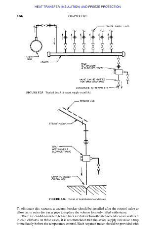
FIGURE 5.25 Typical detail of steam supply manifold.
FIGURE 5.26 Detail of nonreturned condensate.
To eliminate this vacuum, a vacuum breaker should be installed after the control valve to
allow air to enter the tracer pipe to replace the volume formerly filled with steam.
There are conditions where branch lines are distant from the steam header or are installed
in cold climates. In these cases, it is recommended that the steam supply line have a trap
immediately before the temperature control. Each separate tracer should be provided with
Downloaded from Digital Engineering Library @ McGraw-Hill (www.accessengineeringlibrary.com)
Copyright © 2009 The McGraw-Hill Companies. All rights reserved.
Any use is subject to the Terms of Use as given at the website.