
Page 267 - Facility Piping Systems Handbook for Industrial, Commercial, and Healthcare Facilities
P. 267
HEAT TRANSFER, INSULATION, AND FREEZE PROTECTION
HEAT TRANSFER, INSULATION, AND FREEZE PROTECTION 5.51
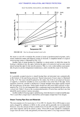
FIGURE 5.21 Heat loss through insulated vessel walls.
the steam on and off or modulate the amount of steam at predetermined set points, and a
steam condensate return and disposal system (if desired). A simplified detail of a typical
steam tracing system is illustrated in Fig. 5.22.
Another type of steam heating for a pipeline is a steam jacket, in which the steam for
heating is introduced into the space between the pipe to be protected and an outer jacket
placed around the pipe for this specific purpose. This is a very costly method, used gener-
ally for precise product temperature maintenance, and is outside the scope of this book.
General
It is generally accepted practice to install tracing lines on horizontal runs symmetrically
at the bottom of the pipe being protected. Typical placement of tracer pipes is illustrated
in Fig. 5.23. The tracer should be placed at the center, but if this is not practical because
of supports, it should be installed as close as possible to the center line of the pipe. Some
engineers, however, consider it satisfactory to install multiple tracer pipes equally around
the circumference of the pipe. Vertical pipe should have the tracer line(s) placed, as illus-
trated in Fig. 5.24. It is recommended that a condensate trap be provided at the base of the
vertical riser. Table 5.18 gives the recommended number of tracer lines and their size that
should be used to protect various size pipes.
Another method of tracing a pipe is spiral tracing, where the tracer is wound around the pipe.
This is used when a single tracer is desired but cannot supply enough heat if run straight.
Steam Tracing Pipe Size and Materials
The most popular size for tracer pipe is 1/2-in (DN 15). Smaller 3/8-in (DN 6) pipe is more
easily plugged by sediment or debris in the system and is generally not recommended.
However, since the amount of heat available from 1/2-in (DN 15) pipe is generally much
more than required, and if the steam is clean, 3/8-in (DN 6) pipe should be considered.
Larger sizes are more costly and generally not necessary unless a very large amount of heat
Downloaded from Digital Engineering Library @ McGraw-Hill (www.accessengineeringlibrary.com)
Copyright © 2009 The McGraw-Hill Companies. All rights reserved.
Any use is subject to the Terms of Use as given at the website.