
Page 265 - Facility Piping Systems Handbook for Industrial, Commercial, and Healthcare Facilities
P. 265
HEAT TRANSFER, INSULATION, AND FREEZE PROTECTION
HEAT TRANSFER, INSULATION, AND FREEZE PROTECTION 5.49
of the pipe for each support. Ten supports multiplied by 9 in equals 90 in, or about 8 ft.
Adding all of the above together:
Basic run of pipe 100 ft (33 m)
Spiraling 50 ft (17 m)
Valve 3 ft (1 m)
Supports 8 ft (2.0 m)
Total 161 ft (53 m) of cable required
Heat Tracing for Indoor Tanks
The information presented previously applies to tanks as well as piping. The pitch most
commonly used for winding the cable around a tank is two revolutions per foot length of
the tank. The design procedure is as follows:
1. Find the area of the tank in square feet. For a square or rectangular tank, multiply the
length, width, and height dimensions of the tank. For a round tank, refer to Table 5.17.
2. Determine the difference in temperature between the tank wall and the ambient air (ΔT).
3. Select the thickness and type of insulation.
4. Refer to Fig. 5.21 to find the heat loss in watts per square foot from the tank. If the insu-
lation is other than fiberglass, use the correction factor in Table 5.6 to find the actual heat
loss. If two lengths of cable are used for each square foot of the tank area, remember to
divide the heat requirements in half to determine the watts per foot of the cable itself.
5. Calculate the amount of heat necessary to replace that lost, and select an electric cable
capable of providing that amount.
Safety Factors
Various safety factors have been included as part of the design criteria. The water mainte-
nance temperature of 40°F is used, which gives a safety factor of 8°F. Table 5.17 has a built-
in safety factor of 10 percent. Additional safety factors are not necessary or economical.
STEAM TRACING
For several reasons, steam is the most practical and economical method to provide heat to piping
systems. Being a gaseous vapor, steam is easy to distribute—it requires no pumping, and because
it is under pressure, it can be piped to remote locations in lines of relatively small diameter.
A steam tracing system consists of a pipe of small diameter (carrying the steam) attached
to the outside of the pipe being protected, a connection to an adequate steam supply, a pressure-
reducing valve assembly from the steam supply if required, a control valve or device to turn
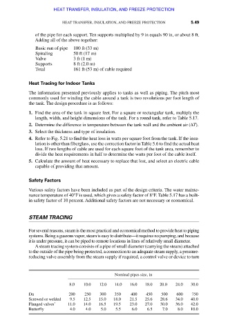
Nominal pipes size, in
8.0 10.0 12.0 14.0 16.0 18.0 20.0 24.0 30.0
Dn 200 250 300 350 400 450 500 600 750
Screwed or welded 9.5 12.5 15.0 18.0 21.5 25.6 28.6 34.0 40.0
Flanged valves * 11.0 14.0 16.5 19.5 23.0 27.0 30.0 36.0 42.0
Butterfly 4.0 4.0 5.0 5.5 6.0 6.5 7.0 8.0 10.0
Downloaded from Digital Engineering Library @ McGraw-Hill (www.accessengineeringlibrary.com)
Copyright © 2009 The McGraw-Hill Companies. All rights reserved.
Any use is subject to the Terms of Use as given at the website.