
Page 264 - Facility Piping Systems Handbook for Industrial, Commercial, and Healthcare Facilities
P. 264
HEAT TRANSFER, INSULATION, AND FREEZE PROTECTION
5.48 CHAPTER FIVE
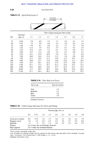
TABLE 5.14 Spiral Pitch Factors P
Feet of pipe tracing per font of pipe
Nominal
DN pipe, in 1.1 1.2 1.3 1.4 1.5 1.6 1.7
13 0.50 5.8 4.0 3.2 2.7 2.4 2.1 1.9
20 0.75 7.2 5.0 4.0 3.4 3.0 2.6 2.4
25 1.00 9.0 6.2 5.0 4.2 3.7 3.3 3.0
32 1.25 11.4 7.9 6.3 5.3 4.7 4.2 3.8
40 1.50 13.0 9.0 7.2 6.1 5.3 4.8 4.3
50 2.00 16.3 11.2 9.0 7.6 6.7 6.0 5.4
65 2.50 19.7 13.6 10.9 9.2 8.1 7.2 6.6
75 3.00 24.0 16.6 13.2 11.2 9.8 8.8 8.0
90 3.50 27.4 18.9 15.1 12.8 11.2 10.1 9.1
100 4.00 30.8 21.3 17.0 14.4 12.6 11.3 10.3
125 5.00 38.1 26.3 21.0 17.8 15.6 14.0 12.7
150 6.00 45.4 31.4 25.1 21.2 18.6 16.7 15.1
200 8.00 59.1 40.8 32.6 27.7 24.2 21.7 19.7
250 10.00 73.7 50.9 40.7 34.5 30.2 27.0 24.6
300 12.00 87.4 60.4 48.2 40.9 35.8 32.1 29.1
TABLE 5.15 Valve Heat Loss Factor
Valve type Heat loss factor
Gate 4.3
Butterfly 2.3
Ball 2.6
Globe 3.9
Courtesy: Raychem.
TABLE 5.16 Cable Footage Allowance for Valves and Fittings
Nominal pipe size, in
0.5 0.75 1.0 1.5 2.0 2.5 3.0 4.0 6.0
Screwed or welded 0.5 0.75 1.0 1.5 2.0 2.5 3.0 4.0 7.0
Flanged valves * 1.0 1.5 2.0 2.5 2.5 3.0 3.5 5.0 8.0
Butterfly 0 0 1.0 1.5 2.0 2.5 2.5 3.0 3.5
Flanges Use 2 times the nominal pipe diameter
Pipe supports Use 3 times the nominal diameter
* Valves include: gate/globe wedge plug.
Note: If cables are spiraled on pipe, use the amount of cable shown times the spiral factor. Example: 2-in gate
valve—(screwed)—2.0 ft. Spiral factor 1.1 ft/ft of pipe 2 × 1.1 = 2.2 ft.
Courtesy: Smith Gates Corp.
Downloaded from Digital Engineering Library @ McGraw-Hill (www.accessengineeringlibrary.com)
Copyright © 2009 The McGraw-Hill Companies. All rights reserved.
Any use is subject to the Terms of Use as given at the website.