
Page 271 - Facility Piping Systems Handbook for Industrial, Commercial, and Healthcare Facilities
P. 271
HEAT TRANSFER, INSULATION, AND FREEZE PROTECTION
HEAT TRANSFER, INSULATION, AND FREEZE PROTECTION 5.55
If the only steam pressure available is higher than that needed for tracing, a steam pressure-
reducing station should be provided. In general, most steam tracing systems use a pressure
of 50 psi (340 kPa) or less.
Steam Supply
Steam for tracing is generally obtained from the facility’s steam service. Normally, saturated
steam is used for tracing purposes. If multiple tracing lines are required, it is standard prac-
tice to connect to the main steam supply once and use a tracer supply manifold, or header,
to feed all the individual tracers. The connections to the header should be made from the
top. This steam supply to the header should have a manual shutoff valve, and each of the
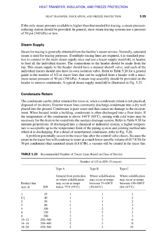
individual tracers should also have its own isolation valve. Refer to Table 5.20 for a general
guide to the number of 1/2-in tracer lines that can be supplied from a header with a maxi-
mum steam pressure of 50 psi (350 kPa). A steam trap assembly should be provided on the
header to remove condensate. A typical steam supply manifold is illustrated in Fig. 5.25.
Condensate Return
The condensate can be either returned for reuse or, when a condensate return is not practical,
disposed of (to drain). Exterior tracer lines commonly discharge condensate into a dry well
placed into the ground. Condensate is pure water and thus causes no damage to the environ-
ment. When located inside a building, condensate is often discharged into a floor drain. If
the temperature of the condensate is above 140°F (60°C), mixing with cold water may be
necessary for the drain to be routed into the sanitary drainage system. Refer to Table 9.30 for
mixture proportions. If discharged into a chemical or industrial system, a higher tempera-
ture is acceptable up to the temperature limit of the piping system and jointing method into
which it is discharging. For a detail of nonreturned condensate, refer to Fig. 5.26.
A problem potentially occurs in the tracer line after the control valve closes. Because the
3
steam in the tracer line will condense to water at a much lower specific volume (0.017 ft /lb for
3
50 psi condensate) than saturated steam (6.8 ft /lb), a vacuum will be created in the tracer line.
TABLE 5.20 Recommended Number of Tracer Lines Based on Class of Service
Number of 1/2-in (DN 15) tracers
Type A Type B Type C
General frost protection Where solidification Where solidification
or where solidification may occur at temps may occur at temps
Product line may occur at temps between 75–150°F between 150–300°F
size, in DN below 75°F (55°C) (55–64°C) (64–147°C)
1 25 1 1 1
1 40 1 1 2
1 2
2 50 1 1 2
3 80 1 1 3
4 100 1 2 3
6 150 2 2 3
8 200 2 2 3
10–12 250–300 2 3 6
14–16 350–400 2 3 8
18–20 450–500 2 3 10
Downloaded from Digital Engineering Library @ McGraw-Hill (www.accessengineeringlibrary.com)
Copyright © 2009 The McGraw-Hill Companies. All rights reserved.
Any use is subject to the Terms of Use as given at the website.