
Page 307 - Facility Piping Systems Handbook for Industrial, Commercial, and Healthcare Facilities
P. 307
SITE UTILITY SYSTEMS
SITE UTILITY SYSTEMS 6.29
7. From data in the form just prepared and using the rational formula [Eq. (6.5)], calculate
the total inflow to each individual DI. Place this information in the form for reference.
The individual pipe from each DI will be sized from this information using the quantity
of rain along with the slope of the pipe.
8. With the total inflow in CFS to individual DIs now known, select the grate type and
size. Consult the manufacturer’s literature for the correct size. Add the grate type to the
above form for reference. Adjust DI locations for flow requirement if necessary. Most
manufacturers have developed inlet flow charts for specific grates. Obtain from their
catalog the size grate that can accept the calculated flow.
9. Layout the piping system from the DI to the point of disposal. Locate MHs. Select the
pipe material.
10. Building roof drain runouts shall be connected to the storm water drainage lines and
their drainage area noted.
11. Select the critical inlet. The critical inlet is the one that produces the maximum combina-
tion of inlet time (overland flow time) plus the flow time in sewer to the very first con-
nection with any other branch. The inlet at the furthest end of the drainage system should
be selected as the starting point. This point will be the longest in time, not necessarily in
distance. This may require some iteration trial calculations of several DIs at various far
ends in order to determine which drainage inlet actually is critical. Distance will not be
the only criteria. An area comprising asphalt which has a fast inlet time might be a much
greater distance from an inlet than an area consisting of grass which would produce a
longer inlet time. The slope and length of sewer pipe must also be considered.
12. With the selection of the critical inlet, the individual sewer pipe line can now be sized
from the critical inlet up to the first point of intersection with any other contributing
source of storm water. The layout of the sewer system will establish the slope of the
pipe, and the form will provide the flow rate of storm water in CFS. The pipe material
will have been selected and value of n for the pipe will be selected (Table 6.3). Entering
Fig. 6.17 knowing the flow in CFS, draw a straight line from the flow rate to the slope
of piping. This will now establish the pipe size and water velocity. Adjust the line to
intersect a standard size. If necessary, make the necessary adjustment as indicated by
the conversion factor if a different n from that of the chart. Multiply the desired figure
by the conversion factor found under the actual “n.” Generally accepted practice assigns
a value of 0.013 to most commonly used pipe materials. Another method of sizing the
pipe would be by using Table 6.26 when a previously determined flow and slope are
known. Good practice uses a one half full pipe.
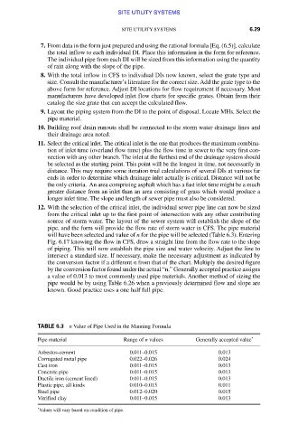
TABLE 6.3 n Value of Pipe Used in the Manning Formula
Pipe material Range of n values Generally accepted value *
Asbestos-cement 0.011–0.015 0.013
Corrugated metal pipe 0.022–0.026 0.024
Cast iron 0.011–0.015 0.013
Concrete pipe 0.011–0.015 0.013
Ductile iron (cement lined) 0.011–0.015 0.013
Plastic pipe, all kinds 0.010–0.015 0.011
Steel pipe 0.012–0.020 0.015
Vitrified clay 0.011–0.015 0.013
* Values will vary based on condition of pipe.
Downloaded from Digital Engineering Library @ McGraw-Hill (www.accessengineeringlibrary.com)
Copyright © 2009 The McGraw-Hill Companies. All rights reserved.
Any use is subject to the Terms of Use as given at the website.