
Page 95 - Facility Piping Systems Handbook for Industrial, Commercial, and Healthcare Facilities
P. 95
PIPING
PIPING 2.45
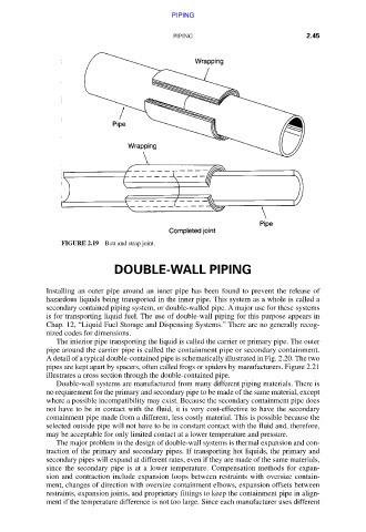
FIGURE 2.19 Butt and strap joint.
DOUBLE-WALL PIPING
Installing an outer pipe around an inner pipe has been found to prevent the release of
hazardous liquids being transported in the inner pipe. This system as a whole is called a
secondary contained piping system, or double-walled pipe. A major use for these systems
is for transporting liquid fuel. The use of double-wall piping for this purpose appears in
Chap. 12, “Liquid Fuel Storage and Dispensing Systems.” There are no generally recog-
nized codes for dimensions.
The interior pipe transporting the liquid is called the carrier or primary pipe. The outer
pipe around the carrier pipe is called the containment pipe or secondary containment.
A detail of a typical double-contained pipe is schematically illustrated in Fig. 2.20. The two
pipes are kept apart by spacers, often called frogs or spiders by manufacturers. Figure 2.21
illustrates a cross section through the double-contained pipe.
Double-wall systems are manufactured from many different piping materials. There is
no requirement for the primary and secondary pipe to be made of the same material, except
where a possible incompatibility may exist. Because the secondary containment pipe does
not have to be in contact with the fluid, it is very cost-effective to have the secondary
containment pipe made from a different, less costly material. This is possible because the
selected outside pipe will not have to be in constant contact with the fluid and, therefore,
may be acceptable for only limited contact at a lower temperature and pressure.
The major problem in the design of double-wall systems is thermal expansion and con-
traction of the primary and secondary pipes. If transporting hot liquids, the primary and
secondary pipes will expand at different rates, even if they are made of the same materials,
since the secondary pipe is at a lower temperature. Compensation methods for expan-
sion and contraction include expansion loops between restraints with oversize contain-
ment, changes of direction with oversize containment elbows, expansion offsets between
restraints, expansion joints, and proprietary fittings to keep the containment pipe in align-
ment if the temperature difference is not too large. Since each manufacturer uses different
Downloaded from Digital Engineering Library @ McGraw-Hill (www.accessengineeringlibrary.com)
Copyright © 2009 The McGraw-Hill Companies. All rights reserved.
Any use is subject to the Terms of Use as given at the website.