
Page 96 - Facility Piping Systems Handbook for Industrial, Commercial, and Healthcare Facilities
P. 96
PIPING
2.46 CHAPTER TWO
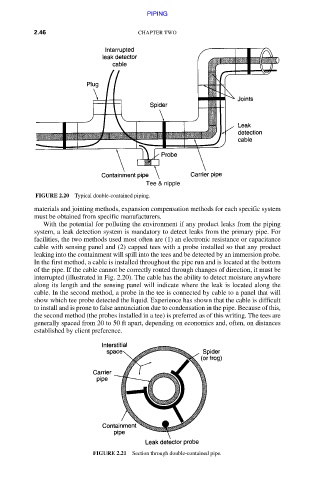
FIGURE 2.20 Typical double-contained piping.
materials and jointing methods, expansion compensation methods for each specific system
must be obtained from specific manufacturers.
With the potential for polluting the environment if any product leaks from the piping
system, a leak detection system is mandatory to detect leaks from the primary pipe. For
facilities, the two methods used most often are (1) an electronic resistance or capacitance
cable with sensing panel and (2) capped tees with a probe installed so that any product
leaking into the containment will spill into the tees and be detected by an immersion probe.
In the first method, a cable is installed throughout the pipe run and is located at the bottom
of the pipe. If the cable cannot be correctly routed through changes of direction, it must be
interrupted (illustrated in Fig. 2.20). The cable has the ability to detect moisture anywhere
along its length and the sensing panel will indicate where the leak is located along the
cable. In the second method, a probe in the tee is connected by cable to a panel that will
show which tee probe detected the liquid. Experience has shown that the cable is difficult
to install and is prone to false annunciation due to condensation in the pipe. Because of this,
the second method (the probes installed in a tee) is preferred as of this writing. The tees are
generally spaced from 20 to 50 ft apart, depending on economics and, often, on distances
established by client preference.
FIGURE 2.21 Section through double-contained pipe.
Downloaded from Digital Engineering Library @ McGraw-Hill (www.accessengineeringlibrary.com)
Copyright © 2009 The McGraw-Hill Companies. All rights reserved.
Any use is subject to the Terms of Use as given at the website.