
Page 151 - Failure Analysis Case Studies II
P. 151
136
the extent of the bottom shell fracture, the remaining intact and partially fractured structures would
have experienced higher than designed stresses. This situation would have been aggravated by the
entry of sea-water into the shell, which would, of course, have cooled the internal members. These
factors, together with the presence of sharp crack tips, resulted in the progressive failure of these
members by both ductile and brittle fracture mechanisms. It was unclear whether the side shell
fractures emanating from the port bilge keel connected with those from sites in the secondary
samples, or whether the cracks from these latter two sites were bypassed by subsequent fracture
events. This would seem to be most likely, due to the complex interaction of cracks observed in
these regions. Final separation of the vessel occurred when the deck plates and their associated
longitudinals failed.
3.5. Possible causes of fracture
The fracture mechanics calculations performed using PD6493 (1 980) procedures as described in
[l] (Table 2) showcd that the defect situated in the port bilge keel detail of the primary sample
exceeded the tolerable defect size at - 1 "C for normal operating conditions. These calculations
showed that the combination of (a) the position of the bilge keel defect under the still water bending
moment loading; (b) the influence of the thermal stresses caused by carrying a hot cargo in cold
waters; (c) the effect of high tensile residual stresses, and (d) the wave loading on exiting the ice
field, would have subjected the bilge keel defect to a high applied crack opening displacement.
Hence, there existed some risk of fracture from this defect under normal operation at a sea-water
temperature of - 1 "C or lower.
It was believed that, under rough sea conditions, the strain rate in the defect region could have
been elevated, by wave loading, to levels exceeding K = IO3 N rnm3!'s-'. Under these circumstances,
there would be a decrease in the toughness of the weld in which the defect was situated, which,
when accompanied by relatively high local stresses, would have meant that the defect in the primary
sample exceeded the critical defect size at - 1 "C, and thus fracture would have been highly probable.
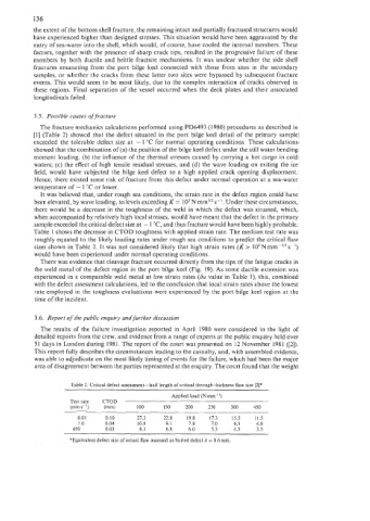
Table 1 shows the decrease in CTOD toughness with applied strain rate. The medium test rate was
roughly equated to the likely loading rates under rough sea conditions to predict the critical flaw
sizes shown in Tablc 2. It was not considered likely that high strain rates (k > 10SNmm-3'2s ')
would have been experienced under normal operating conditions.
There was evidence that cleavage fracture occurred directly from the tips of the fatigue cracks in
the weld metal of the defect region in the port bilge keel (Fig. 19). As some ductile extension was
experienced in a comparable weld metal at low strain rates (Su value in Table I), this, combined
with the defect assessment calculations, led to the conclusion that local strain rates above the lowest
rate employed in the toughness evaluations were experienced by the port bilge keel region at the
time of the incident.
3.6. Report of the public enquiry and further discussion
The results of the failure investigation reported in April 1980 were considered in the light of
detailed reports from the crew, and evidence from a range of experts at the public enquiry held over
51 days in London during 1981. The report of the court was presented on 12 November 1981 ([2]).
This report fully describes the circumstances leading to the casualty, and, with assembled evidence,
was able to adjudicate on the most likely timing of events for the failure, which had been the major
area of disagreement between the parties represented at the enquiry. The court found that the weight
Table 2. Critical defect assessment-half length of critical through thickness flaw size [2]*
Applied load (N mm-2)
Test rate CTOD
(mms-') (mm) 100 150 200 250 300 450
0.01 0.10 27.3 22.8 19.8 17.3 15.5 11.5
1 .o 0.04 10.8 9. I 7.8 7.0 6.3 4.8
450 0.03 8.3 6.8 6.0 5.3 4.5 3.5
*Equivalent defect size of actual flaw assessed as buried defect d = 8.6mm.