
Page 155 - Failure Analysis Case Studies II
P. 155
140
Table I. Major changes made to the manufacture of the piston rods
Original design Final design
~~ ~
Rod steel En84 4%C En9-0 55%C
Rod heat treatment (before welding) Quench and temper None
Rod microstructure Tempered martensite Ferrite/pearhte
Welding method SMAW GTAW
Circumferential butt weld “Rosette weld” added
Surface finish Chrome plating Nitriding
Historically, a number of changes were made to the design and manufacture of the piston rods,
as outlined in Table 1. The steel grade was changed because a change of suppliers-the latter did
not produce En8. The heat treatment of the rods prior to welding was omitted because the as-
received En9 met the hardness specification of the quenched and tempered En8.
3. INVESTIGATION
3.1. Visual inspection
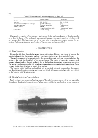
Figures 1 and 2 show the end of a typical piston rod fracture. The very low degree of wear on the
adapter indicated that the actuator had only been in service for a very short period of time.
The cracks appeared to have originated in the centre of the weld and then propagated along the
centre of the weld for about half of the circumference. The cracks subsequently branched and
propagated axially along the rod, probably due to the bending stresses that arise during operation.
The fracture surface appeared brittle with large elongated grains being clearly distinguishable. There
were no visible signs of fatigue or plastic deformation.
The “rosette welds” had fractured and had not, as was their intended purpose, held the adapter
and the piston rod together once the main weld had failed. A large amount of porosity was evident
on the “rosette weld” fracture surface.
3.2. Chemical analysis and mechanical tests
Spark emission spectroscopy of various parts of the failed components, as well as raw materials,
showed that the chemical compositions of all parts were within the specifications for the respective
Fig. 1. Typical failed actuator piston rod showing the adapter, the circumferential weld and a large crack