
Page 159 - Failure Analysis Case Studies II
P. 159
144
Table 2. Ni and Cr equivalents calculated on average nominal compositions
Steel grade Ni equivalent Cr equivalent
En9 16.8 0.5
En32 (uncarburised) 4.8 0.5
E312 13.8 30.0
ER 70s-6 5.2 1.5
place, the former composition was more likely. Indeed, the microstructure of the E3 12 weld consisted
mainly of austenite and ferrite (Fig. 3), but a large degree of grain boundary and intragranular
carbide precipitation, probably chromium carbides, was also observed. The carbide precipitation
probably took place during nitriding, resulting in the high hardness of the weld and weakening of
the grain boundaries.
The high residual stresses (estimated at 300-500 MPa) due to the different thermal expansion
coefficients of the duplex weld metal and the low alloy parent metal (11-13 x 10-6/K and 16-
18 x 10-6/K for En9 and high Cr/high Ni steels respectively), coupled with the highly constrained
joint configuration and the weakened microstructure, probably resulted in cracking of the weld on
cooling after nitriding. This conclusion is supported by the fact that the actuator piston rods that
were phosphated did not fail-there was no thermal cycle to allow for carbide precipitation.
Unfortunately, no phosphated piston rods were available for evaluation, so this could not be
confirmed.
The absence of preheat resulted in a very high cooling rate which had a twofold effect. Firstly,
the HAZ was very hard and susceptible to cold cracking which was confirmed by the martensitic
structure and some small cracks found in the HAZ. Although the nitriding subsequently tempered
this microstructure to 200 Hv, the delay between welding and nitriding was often several days which
was sufficient for damage to occur. Secondly, the weld microstructure comprised long, narrow grains
with no equiaxed grains near the centreline. The result was increased weld centreline segregation and
reduced toughness.
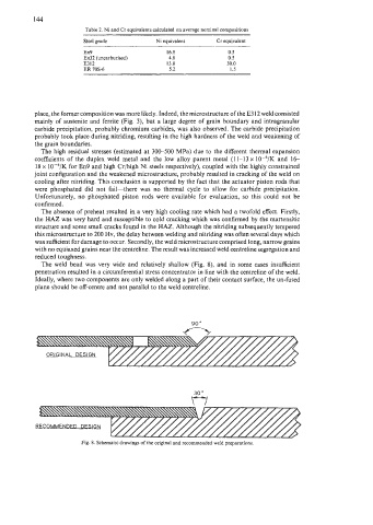
The weld bead was very wide and relatively shallow (Fig. 8), and in some cases insufficient
penetration resulted in a circumferential stress concentrator in line with the centreline of the weld.
Ideally, where two components are only welded along a part of their contact surface, the un-fused
plane should be off-centre and not parallel to the weld centreline.
Fig. 8. Schematic drawings of the original and recommended weld preparations.