
Page 204 - Failure Analysis Case Studies II
P. 204
189
area was recognized as a prime site for fatigue failure initiation, and de Havilland subsequently
redesigned the windows and increased the thickness of the skin in these areas to prevent this
occurring on later Comet aircraft. The stress around a cut-out was shown to be over 3 times the
remote stress due to cabin pressurization both experimentally [2J and theoretically [3]. Using the S-
N data available at the time, it was possible to explain the shortened fatigue life.
3. ANALYSIS OF THE FAILURE
It is of interest to use fracture mechanics analyses (not used in 1954) to give an insight into the
relative importance of the factors which combined to produce the catastrophic failure.
The bolthole which was the origin of the failure in Yoke Peter was over 50mm from the ADF
window (Fig. 4), and the stress in this area was significantly below the maximum stress at the ADF
window itself. In fact, as part of the RAE investigation, strain gauges were placed around areas
such as the ADF windows on Yoke Uncle to examine the stresses in this area. The stress in the
vicinity of the bolthole was calculated to be around 70 MPa, compared to 315 MPa around the edge
of the windows. This stress is reasonably close to that expected as a general level for a pressurized
cylinder of 1.6m radius, and a thickness of 1.42mm. This thickness is derived from the 0.71 mm (22
gauge) skin and 0.71 mm thick doubler plate around the ADF window. Although the crack grew
principally towards the ADF window, the stresses in this area were shown, using strain gauges, not
to vary much, and the crack was only 25 mm long when failure occurred [2].
If it is assumed that linear elastic fracture mechanics can be applied, use may be made of the Paris
law
da
_-
dN - AAK".
However, to begin such an analysis it is necessary to obtain fatigue crack growth data for this
particular alloy. The alloy in question is DTD 546B, an aluminium-coated high tensile strength
aluminium alloy for sheet use containing between 3.5 and 4.5% copper [4]. This alloy was developed
before fatigue crack growth plots were taken for materials, but data can be obtained from the actual
fatigue of Comet I G-ALYR (Yoke Robert) in a water tank at the RAE [5].
A number of cracks were monitored on Yoke Robert propagating from the rivets near corners
of the cabin windows, and the data given as plots of number of cycles against crack length.
Yoke Robert underwent 11,313 cycles, and cracks were prevented from further growth at a length
of 165mm, as this was felt to be the length at which cracks would propagate to failure within a
few more cycles. This gives a fracture toughness of around 35 MPam'I2. Using the strain gauge
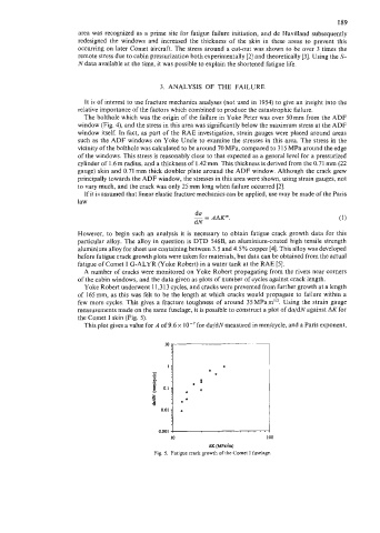
measurements made on the same fuselage, it is possible to construct a plot of da/dN against AK for
the Comet I skin (Fig. 5).
This plot gives a value for A of 9.6 x lo-' for da/dNmeasured in mm/cycle, and a Paris exponent,